



Each of the three assets is easy to justify alone. Solar panels cut the energy bill. A battery cuts the demand charge and firms the solar. EV chargers serve a growing fleet or a revenue-generating amenity. Add them together on one site and something more interesting emerges than three parallel projects: a commercial microgrid - an integrated energy system with its own generation, storage, flexible load and, if designed for it, the ability to keep running when the grid does not.
The integration is also where projects go wrong. Sized independently, the three assets fight: the chargers create an evening peak the solar cannot touch, the battery charges from the grid at midday while solar curtails, and the interconnection application sized for the original building now falls short of everything. This playbook treats the three as one design problem, and walks the decisions in the order they actually constrain each other. It draws on - and links out to - the deep dives on EV charging with battery storage, behind-the-meter microgrids and grid-forming operation, which cover the individual systems in detail.

Step One: The Interconnection Budget Decides Everything
Before any equipment is selected, establish the site's real import limit and the process for changing it. Everything else is allocation.
Three loads and one generator now share a single point of interconnection: the building's existing load, the new EV charging load, the battery in both charge and discharge modes, and the solar exporting or offsetting. The utility sees only the net. The design question is how to spend the available headroom - and the honest answer, in most urban and suburban sites, is that the available headroom is smaller than any one of the three new assets would like.
The budget exercise is simple in principle: list the building's historical maximum, add the coincident charging demand at maturity, add the battery's charging draw, subtract the minimum expected solar, and compare with the service limit. Most sites discover a gap, and the gap determines the strategy: managed charging to compress the charger demand, a battery to buffer it, phased deployment to stay under the limit while the utility upgrade works through its queue, or some combination. Our guide to fleet depot charging works this arithmetic for the fleet case in detail.
File the interconnection enquiry early regardless of the plan - the queue time it reveals is the project's true critical path, and every other decision should be scheduled around it.
Step Two: Get the Ratios Coupled, Not Independent
Sizing the three assets together produces different numbers than sizing them apart, because each asset changes the optimal size of the others.
Solar is sized by energy economics and roof reality, but its usable share depends on load coincidence. A site with heavy daytime demand consumes solar directly; a site with a flat load and big evening peaks will export or curtail much of the array's output unless the battery absorbs it. In markets with weak export compensation, the battery is what makes a larger array pay.
Storage is sized by the residual problem - and in this triad the residual is mostly the evening EV peak plus the cloud transients the solar cannot cover. A charger bank drawing 300 kW into the evening is exactly the demand the battery must shave, and exactly the demand solar cannot reach. Size the battery against the net-load curve (site load plus charging, minus solar), on the worst production days, with the transient reserve our control algorithms article describes.
Charging is sized by demand, not by ambition. The number of chargers is a business decision, but their kilowatts are an interconnection decision. Managed charging - spreading sessions across dwell time - reduces the coincident demand substantially before any hardware answer is needed, and should be counted as capacity in the budget before the battery is sized.
A workable first-pass ratio for many commercial sites lands near one megawatt of charging served by 400 to 600 kW of solar and 500 kWh to 1 MWh of storage, but the honest number comes only from the site's own coincident curves. Treat any rule of thumb as a starting hypothesis to be tested against interval data.
Step Three: The Control Architecture Is the Actual Product
Three assets from three vendors, each with its own controller, is a systems integration project wearing a procurement costume. The control design should be settled conceptually before equipment is chosen.
Three layers, in ascending scope:
Asset controllers - the solar inverter, the battery EMS, the charge point management system - each optimising within its own equipment. These exist regardless and are supplied with the hardware.
A site controller (the microgrid controller) that sits above them, owning the tariff logic, the interconnection limit, the dispatch priorities and the measurement at the point of common coupling. This is the layer that decides, every second, whether solar serves the chargers, the battery charges or discharges, and what the meter sees. Selecting and specifying this controller is a procurement decision in its own right - our piece on microgrid controller selection covers the evaluation criteria.
A market or aggregation interface, where demand response, virtual power plant participation or flexibility market signals enter. Not every site needs it on day one, but the site controller should expose it, because retrofitting market access into a closed controller is slow.
The dispatch priority stack for this triad is well established: serve building and charging load from solar first; keep battery charging inside solar surplus; hold the demand setpoint at the meter with battery discharge; preserve the resilience reserve; and only then export or arbitrage. Sites that skip the explicit priority stack get the default behaviour of whichever vendor's controller was installed last - and that behaviour is rarely the one the financial model assumed.

Step Four: Stack the Revenue Honestly
The integrated site earns from multiple streams, and the playbook discipline is attributing each stream to the asset that earns it - because that attribution is what the financial model, and eventually the contract negotiation, depends on.
Solar earns energy savings and, where export is paid, export revenue. The battery earns demand charge reduction at the meter, TOU arbitrage, and potentially grid services - but every kilowatt-hour reserved for resilience or for charger buffering is a kilowatt-hour not earning in the market. The chargers earn charging revenue or fleet savings, and their demand contribution is a cost the other two assets are there to absorb.
The integration premium is real and should be claimed explicitly in the model: the battery that would be undersized for the site's building load alone is justified by the charger demand; the array that would curtail without storage is fully utilised because of it; the interconnection upgrade both would have needed is avoided by the pairing. Model the three together or the model will be wrong - usually pessimistically, occasionally optimistically, and always expensively.
Step Five: Build in Phases, Design in Whole
Phased delivery keeps capital exposure manageable and lets each phase de-risk the next, but the design must be done for the end state from day one.
The sequence that works: measurement first - a month of interval data plus a charging demand study. Solar second, sized with the end-state in mind, with conduit, switchgear ways and space provisioned for the rest. Storage and charging third, as one procurement, because they solve each other's problem and share the interconnection headroom. Islanding last, if at all - the ability to run disconnected from the grid adds grid-forming capability, transfer switching and a fresh layer of utility negotiation, and is best added once the base system has operating history. Our grid-forming microgrid article covers what that step actually requires.
Two phase-boundary disciplines prevent the classic integration failures. Provision generously in phase one - spare switchgear ways and cable routes are cheap at construction and expensive as retrofits. And freeze the site controller architecture at phase one, choosing a platform known to accept all three asset types, even if only one is connected.
Step Six: Compliance, Safety and the Utility Relationship
Three assets mean three permitting tracks and one relationship that matters most: the utility's.
Interconnection approval for the solar, the storage and the chargers is usually three separate processes with different forms, studies and timelines - and the storage interconnection is the one most often underestimated, because batteries both draw and inject and must satisfy anti-islanding, ride-through and protection coordination requirements. Fold all three applications into one project schedule with one owner, and engage the utility's interconnection team early enough that their studies sequence rather than collide.
On safety, the aggregation multiplies the documentation: fire code compliance for the battery, rapid shutdown and arc-fault rules for the array, and charging-area requirements for the chargers, each with its own inspector and its own checklist. A single compliance matrix, maintained from design through commissioning, is unglamorous and indispensable.
The Playbook, Compressed
Measure the load and the headroom. File the interconnection enquiry. Size the three assets against the coupled net-load curve, not independently. Buy the site controller as deliberately as the hardware. Attribute every revenue stream to the asset that earns it. Build in phases but design for the end state. Keep the utility close and the compliance matrix current.
None of these steps is difficult; the failure mode is doing them in the wrong order, or doing them separately. A commercial microgrid built by this sequence behaves as one system from its first day of operation - and the difference between that and three loosely coupled projects is, in the end, most of the return.

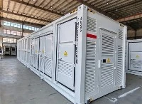
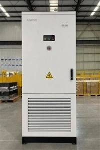
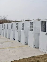
125KW 241kWh Battery Energy Storage System Cabinet
The BESS 125KW 241kWh Lithium Battery Energy Storage Cabinet is a high-power, large-capacity integrated energy storage solution engineered for medium-to-large commercial, industrial, and utility-scale applications. It integrates a 125kW high-performance bidirectional inverter, a 241kWh lithium iron phosphate (LiFePO4) battery bank, and a full-featured intelligent energy management system (EMS) into a modular cabinet design. This system enables efficient renewable energy storage, peak shaving, load shifting, grid frequency regulation, and emergency backup power supply. Ideal for large factories, shopping malls, industrial parks, utility-scale solar/wind farms, and microgrids, it enhances energy independence, reduces high grid demand charges, and supports the stable integration of high-penetration renewable energy into the grid.