



A DC fast charging hub presents a sizing problem that looks simpler than it is. Four 150 kW chargers, 600 kW of installed capacity, a site connection that can supply perhaps 200 kW. The gap is obvious. Fill it with a battery. The question is how much battery - and the answer is not "the difference" in any straightforward sense, because the chargers almost never deliver their rated power all at once, and the billing metric is not instantaneous power.
Getting this wrong in either direction is expensive. Undersize the buffer and the site either throttles vehicles during busy periods - which costs sessions, reviews and repeat custom - or trips the demand limit and pays for it all month. Oversize it and capital sits idle, because a buffer sized for a scenario that occurs twice a year delivers no revenue on the other 363 days.
This article sets out the sizing arithmetic for EV charging peak shaving at public and retail fast-charging sites. It is narrower than our overview of EV charging with battery storage, which covers the business models, and distinct from our fleet depot guide, which deals with the different problem of overnight fleet charging. Here the question is specifically: how many kilowatts and kilowatt-hours of buffer does a fast-charging hub need?

First: Installed Power Is Not Demand
The most common sizing error is to subtract the site limit from the sum of charger nameplates. That produces a buffer roughly three times larger than necessary.
Four 150 kW chargers do not draw 600 kW. Three factors cut the actual demand:
Simultaneity. At a four-stall hub, the average number of vehicles charging at once is typically 1.2 to 2.0 during busy periods, and the chargers' own power-sharing architecture often limits the total anyway. A 600 kW installed site may see a 300 kW coincident peak.
Vehicle acceptance rate. A 150 kW charger only delivers 150 kW to a vehicle that accepts it. Many cars taper above 80 percent state of charge, and some models cap at 100 or 120 kW regardless of the charger. The charger's rating is a ceiling, not a prediction.
Session shape. A fast-charging session is a curve, not a plateau - high power for the first ten to fifteen minutes, then tapering. The peak draw is brief, and the energy-weighted average is much lower.
The right input is not the nameplate but a session-level model: arrival rate by hour, dwell time, vehicle acceptance curve, and the charger's power-sharing logic. Where a hub has operating history, that data replaces the model entirely. Where it does not, a conservative simultaneity assumption and a sensitivity check are the minimum.

The Three Numbers That Size the Buffer
With a realistic coincident load curve in hand, the buffer size falls out of three numbers.
The power gap. The difference between the hub's coincident charging demand and the site's import limit. If the coincident peak is 300 kW and the limit is 200 kW, the gap is 100 kW - and that is the buffer's minimum power rating, not its energy rating. Note the distinction: exceeding the limit for even a few minutes can set a demand charge, so the buffer must respond fast, which is a PCS rating question rather than a capacity one.
The energy per burst. What the buffer must deliver before it can recharge. A single 20-minute session at 150 kW delivers about 50 kWh; two vehicles back-to-back at reduced power might draw 60 to 80 kWh from the buffer over half an hour. Multiply by the number of consecutive sessions the site must serve at full speed before a lull allows recharging - typically two to four at a busy urban hub.
The recharge window. How quickly the buffer can refill without breaching the limit itself. If the site has 200 kW of import capacity and the hub's base load is 30 kW, the buffer can recharge at roughly 170 kW minus whatever the chargers are drawing. A 300 kWh buffer refilling at 100 kW net takes three hours - fine for a hub with a midday lull, impossible for one with continuous demand.
The buffer must satisfy the power gap, the burst energy, and the recharge constraint simultaneously. Sizing on energy alone produces a battery that cannot deliver fast enough; sizing on power alone produces one that runs flat during the second consecutive session.
The Billing Interval Trap
Demand charges are billed on an interval - commonly 15 minutes, sometimes 5 or 30. The buffer's job is to hold the average over that interval below the limit, not to hold instantaneous power below it. That distinction cuts both ways and is frequently mishandled.
On one hand, it relaxes the requirement: a 30-second spike above the limit, absorbed partly by the buffer and averaged out over the interval, may not set the billed demand at all. On the other, it means the control loop must integrate energy over the interval rather than chase an instantaneous setpoint - and a buffer controlled on instantaneous power will over-discharge on transients it did not need to cover.
The practical specification is to require the control system to manage the interval average explicitly, with the interval length configured to the tariff. This is the same discipline described in our peak shaving control algorithms article, applied to a load that changes faster than any building's.
Utilization and the Queue Trade-off
Buffer sizing is not only an electrical question; it is a service-level decision with a revenue consequence.
A hub with a small buffer can still serve all its vehicles, but must throttle them during busy periods - reducing delivered kilowatts per session, lengthening dwell time, and creating queues. Whether that matters depends on the site: a retail hub where drivers stay 25 minutes anyway can tolerate throttling; a highway corridor where the promise is "20 minutes to 80 percent" cannot.
The trade-off should be modelled explicitly: for a given buffer size, what share of sessions falls below the advertised charging speed, and what is the revenue or reputation cost of that? In practice, hubs sized to protect the advertised speed on the busiest 95 percent of days carry a buffer roughly 20 to 40 percent larger than one sized on average demand - a premium that is usually justified at high-traffic sites and rarely justified at low-traffic ones.
There is also an operational lever that reduces the buffer requirement: smart queueing. Sequencing sessions so that no more than the available power is drawn at once, rather than letting all stalls pull simultaneously, flattens the hub's demand curve substantially. Software first, hardware second - the same principle that applies to fleet depots.
Two Operating Modes, One Battery
The buffer runs two distinct modes, and the design must serve both.
Peak shaving: discharge when hub demand exceeds the limit, fast, to the interval average target. This is the high-power mode and sets the PCS rating.
Recharge: absorb energy during low-demand windows - overnight, or midday lulls - at whatever rate the remaining headroom allows. This sets the energy rating in combination with the burst requirement, and it is where an integrated solar array can contribute, charging the buffer without touching the import limit.
A buffer designed only for the first mode will be too small in energy; one designed only for the second will be too slow. The specification should state both power and energy requirements with the duty cycle behind them, and the warranty should cover that duty - fast charging buffers see high-C-rate cycling that a standard commercial cabinet warranty may not anticipate.
What Else the Site Must Get Right
Three supporting details decide whether the sizing translates into performance.
Transformer and protection capacity. The buffer shares the transformer with the chargers. Its discharge does not pass through the transformer, but its recharge does, and the protection settings must accommodate both directions. Confirm that the existing protection coordination covers a bidirectional source.
Metering and settlement. If the hub sells charging by the kilowatt-hour, the meter must account for energy that came from the buffer rather than the grid, and the tariff accounting must not double-count it. This is a commercial configuration issue as much as a technical one.
Thermal environment. A buffer working at high C-rate in a hot, unshaded charging canopy area will derate. The cooling specification should reflect the actual duty and ambient, not a nominal rating - the subject of our liquid versus air cooling comparison.
The Sizing Sequence
Model the session-level demand curve from arrival rates and vehicle acceptance, not from charger nameplates. Establish the site's import limit and billing interval. Compute the power gap, the burst energy and the recharge constraint. Choose the buffer size that satisfies all three at the service level the site promises. Confirm the control system manages interval averages, and that the warranty covers the duty.
Then check the answer against cost: if the buffer required to protect the advertised speed is disproportionately expensive, the honest options are to reduce installed charger power, add smart queueing, accept managed throttling at peak, or accept a longer interconnection process. All four are legitimate; only the fifth - buying an undersized buffer and hoping - is not.
A fast-charging hub is a power-constrained business wrapped in a real-estate asset. The buffer battery is what lets it sell the service it advertises, and the sizing arithmetic above is what keeps that buffer from becoming either a bottleneck or a monument.
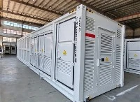
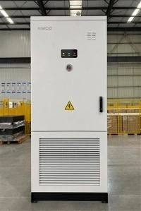
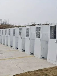
Liquid Cooling 125KW 261kWh Lithium Battery Energy Storage Cabinet
The IP55 Protected All-in-One Solar Energy Storage Cabinet is a high-performance, integrated energy solution engineered for outdoor commercial, industrial, and utility-scale solar applications. It integrates a 125kW Power Conversion System (PCS), a 261kWh lithium iron phosphate (LiFePO4) battery bank, an advanced liquid cooling system, and a intelligent Battery Management System (BMS) into a single cabinet with IP55 weatherproof protection. Designed to withstand harsh outdoor environments while delivering efficient energy conversion and storage, it supports solar energy absorption, peak shaving, load shifting, grid auxiliary services, and emergency backup power. Ideal for utility-scale solar farms, industrial parks, large commercial complexes, and remote microgrids, it provides a reliable, space-saving, and low-maintenance solution for large-scale renewable energy integration.
