


Project Background: A Factory's "Electricity Anxiety"
Chad is located in northeastern Africa, boasting abundant solar irradiance with an annual global horizontal irradiation above 2200 kWh/m², making it a naturally favourable region for photovoltaic power generation. At the same time, however, the reliability of the municipal power grid has long been a headache for industrial consumers.

The owner of this project is a manufacturing factory in Chad with an on-site transformer rated at 1500 kVA and a peak production load of approximately 800 kW. What drove the owner to invest in a solar-plus-storage retrofit was not the electricity tariff itself, but the inconsistent municipal power supply. The grid only supplies power for roughly 6 to 8 hours per day, and the supply window is unpredictable - sometimes power arrives in the daytime, sometimes in the middle of the night. This makes it impossible for the factory to arrange production shifts reliably. Sudden grid outages shut down production motors, variable frequency drives, air compressors, lighting and monitoring systems all at once. The resulting losses to continuous production far exceed electricity costs. The owner's core requirements are clear: deploy an energy storage system capable of stable daily discharge of 3200 kWh to cover production loads during grid blackouts. The storage system must implement upper and lower state-of-charge (SOC) limits to prevent overcharging and over-discharging.
Operate alongside solar PV for self-consumption during daytime hours, with surplus power used to charge the batteries;
With a 1500 kVA transformer and 800 kW peak load, the total output of the integrated system must stay within this boundary;
Automatically switch back to mains supply once grid power is restored, with no manual attendance required.
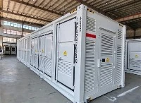
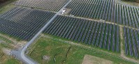
Based on these requirements, our proposed solution consists of an 800 kWp PV array + 2 × 500 kW hybrid inverters + 2 × 2.411 MWh containerised energy storage systems, forming a grid-tied and off-grid solar-storage microgrid with automatic mode transition.
Load and Power Consumption Profile Analysis
We first mapped out the factory's electricity consumption profile before finalising the design. The 1500 kVA transformer delivers an active power capacity of around 1350 kW at a power factor of 0.9. The factory's peak load stands at approximately 800 kW, leaving roughly 40% spare capacity on the transformer. This provides ample headroom for PV grid connection and battery charging/discharging. The key target specified by the owner is a daily discharge volume of 3200 kWh. Simple back-calculation shows that if the factory operates at an average load of 600–700 kW for 4–5 hours during outages, the daily discharge falls within the range of 2800–3500 kWh. This means the energy storage system is not merely for peak shaving, but must act as the primary power source through the entire outage window. This requires sufficient capacity margin in the battery system. If the full rated capacity is routinely discharged, the battery will suffer deep discharge repeatedly and its service life will degrade rapidly. Conversely, overly conservative discharge will fail to meet production needs. This is why the owner mandated fixed upper and lower SOC thresholds.
Overall System Configuration

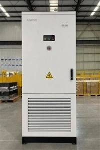
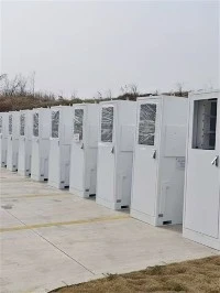
The whole system is made up of four subsystems. The photovoltaic subsystem adopts 1230 pieces of 650 W monocrystalline modules with a total capacity of around 800 kWp; its main function is to generate electricity during daytime, supply power to onsite loads on priority, and charge batteries with surplus power. The hybrid inverter subsystem includes two 500 kW three-phase inverters with a maximum output of 550 kW, responsible for DC‑AC conversion and dual-mode grid-tied / off-grid operation. The containerised energy storage subsystem is configured with two sets of 2.411 MWh LFP storage containers, delivering a total capacity of 4.822 MWh for peak shaving and power supply to loads during grid outages. The monitoring and EMS subsystem consists of a local touchscreen and remote communication modules, which perform power dispatch among photovoltaic modules, batteries and the utility grid.
The AC side of the system connects to the factory's 400 V low-voltage busbar. Mains power, PV generation, battery storage and loads converge on the same bus. The built-in static transfer switch (STS) inside the hybrid inverters handles grid-tied / off-grid switching within milliseconds, so production equipment will not reboot due to power interruption.
PV Array Design: Stringing Layout for 1230 Modules
N-type monocrystalline 650 W modules are selected. Key parameters: maximum power voltage ~41.3 V, maximum power current ~15.7 A, open-circuit voltage ~49.5 V, short-circuit current ~16.6 A, open-circuit voltage temperature coefficient ~ -0.25%/℃. Chad features hot daytime conditions, while nighttime temperatures can drop to around 15 ℃. Under the extreme low-temperature condition of 10 ℃, open-circuit voltage rises by approximately 4%, bringing the module open-circuit voltage to roughly 51.5 V.
19 modules per string: open-circuit voltage ~978 V, below the inverter's maximum DC input voltage of 1000 V, complying with safety requirements.
14 modules per string: open-circuit voltage ~721 V, falling within the inverter MPPT operating range of 250–850 V, which is also acceptable.
Final module allocation:
Hybrid Inverter #1 (500 kW): 33 strings in total
32 strings × 19 modules = 608 modules
1 string × 14 modules = 14 modules
Total: 622 modules
Hybrid Inverter #2 (500 kW): 32 strings in total
32 strings × 19 modules = 608 modules
Total: 608 modules
The sum of 622 + 608 = 1230 modules matches the procurement quantity exactly with no surplus. For MPPT parallel connection, a maximum of 2 strings are paralleled on each MPPT track. With a short-circuit current of 16.6 A × 2 = 33.2 A, the value is far below the maximum allowable input current per MPPT track, ensuring DC-side safety.
Detailed layout:
Inverter #1: 12 MPPT tracks. 11 tracks each carry 2 parallel strings of the standard 19-module configuration. The remaining single track connects the special 14-module string separately. This arrangement avoids mismatched voltage levels between the 14-module and 19-module strings, which would otherwise drag down the output of the lower-voltage string if connected on the same MPPT channel.
Inverter #2: 12 MPPT tracks, each with 2 parallel standard 19-module strings in a symmetrical layout for easier maintenance.
This design delivers a clear DC architecture for both inverters, allowing field technicians to quickly identify faulty strings during inspections.
Hybrid Inverter Selection Rationale

The two 500 kW hybrid inverters serve as the "heart" of the whole system. Unlike conventional grid-tied inverters, they are integrated cabinet units embedding MPPT, built-in transformer, STS automatic transfer, maintenance bypass, three-phase unbalanced output capability and EMS communication. Several core functions are critical for this project:
Dual grid-tied / off-grid mode: When mains power is available, the unit works as a grid-tied inverter; PV power feeds loads directly and charges the battery. Once the grid fails, it switches instantly to off-grid mode and establishes a stable 400 V / 50 Hz voltage and frequency reference to supply the factory from the battery.
Three-phase unbalanced output: Factory loads are not always symmetrical; lighting and socket loads are often concentrated on a single phase. This inverter tolerates unbalanced three-phase output and will not shut down due to single-phase overload.
Multi-unit parallel operation: The two inverters can run in parallel with a combined output capacity of 1000 kW, comfortably covering the factory's 800 kW peak load and leaving around 20% margin for future expansion.
Maintenance bypass: During later servicing, loads can be transferred to mains supply via the bypass cabinet while the inverter is isolated for maintenance without disrupting production.
IP20 protection rating, air-cooled, indoor installation: Operating temperature range of -30 ℃ ~ +55 ℃, fully compatible with the high ambient temperatures inside the equipment room in Chad.
Energy Storage Configuration and SOC Control Strategy

The system automatically cycles between four operating modes without manual intervention:
Mode 1: Grid available + sufficient daytime solar irradiance PV power supplies loads first. Surplus generation charges the battery. If the battery reaches full SOC and PV continues to generate excess power, the EMS will curtail PV output smoothly to prevent reverse power flow into the utility grid (reverse power injection is strictly regulated locally).
Mode 2: Grid outage + daytime The inverter switches to off-grid mode within milliseconds. PV continues to power loads and charge the battery. If PV output exceeds load demand, excess energy is stored in the battery; if PV generation is insufficient, the battery supplements the power gap.
Mode 3: Grid outage + night / cloudy weather The battery discharges independently following the pre-set SOC profile until grid power resumes or the battery hits the lower SOC limit.
Mode 4: Grid restoration Once the controller detects stable voltage and frequency from the utility supply, the inverter automatically transitions back to grid-tied operation. The EMS determines whether the battery continues charging based on the control strategy.
The whole transition is transparent to factory operators: lights remain on, motors keep running and PLCs do not restart.

Why This Configuration Instead of Alternatives
A common question arises: the owner only needs 3200 kWh daily discharge, so why deploy two 2.411 MWh containers instead of one? The decision comes from practical engineering considerations:
Redundancy: With two containers operating in parallel, if one unit fails, the other can still deliver approximately 1.2 MWh of energy, preventing an unplanned factory blackout.
Cycle life: Limiting daily discharge depth to 75% rather than 90% extends the battery cycle life from 6,000 cycles to over 8,000 cycles, improving whole-life economics.
Power matching: The discharge capacity of each 2.4 MWh container pairs well with the two 500 kW inverters, providing sufficient DC-side margin and avoiding inverter derating caused by battery voltage fluctuation.
Why specify 800 kWp of PV? Chad has strong solar irradiation. The 800 kWp array delivers an average output of 500–600 kW during effective sunshine hours. This directly covers daytime load demand and recharges the battery throughout the day, reducing reliance on grid charging.
Project Value
The biggest change after commissioning is not simply electricity cost savings, but the ability to fully schedule production.
Grid outages are no longer treated as production emergencies and become part of normal daily operation;
Daytime PV generation covers midday peak loads and reduces the factory's dependence on municipal power;
Batteries act as a backup power source for sudden outages and protect semi-finished goods on production lines;
Remote monitoring via EMS allows the owner to check the status of individual battery packs and PV strings on a mobile device;
Grid connection cabinets and connection points are reserved, supporting seamless capacity expansion by adding extra inverters or battery containers as the factory scales up.
In regions such as Chad with abundant solar resources but unstable grids, solar-plus-storage is not a discretionary upgrade but an essential requirement for continuous manufacturing. The 800 kW PV array provides power in the daytime, the 4.8 MWh storage ensures on-demand power availability at any time, and the two 500 kW hybrid inverters enable seamless transition between power sources. Together, they form a complete industrial microgrid.

500KW/1MW 1MWh/2MWh Battery Energy Storage System Container
The 500kW/1MW 1MWh/2MWh Battery Energy Storage System Container is a turn‑key utility‑grade energy storage solution housed in standard 20ft or 40ft shipping containers, integrating bidirectional PCS, A‑grade LiFePO4 battery clusters, master BMS, liquid‑cooled thermal management, gas fire suppression, high‑voltage distribution and EMS energy management system with full factory pre‑assembly and pre‑commissioning. Requiring only foundation construction and high‑voltage cable connection for on‑site commissioning, it supports flexible power‑capacity configuration and multi‑container parallel expansion, delivering core capabilities of peak‑shaving and load shifting, renewable energy smoothing, frequency‑voltage grid support, islanded micro‑grid operation and large‑scale emergency backup. Featuring IP54 enclosure protection and comprehensive multi‑layer safety mechanisms, it adapts to diverse harsh outdoor environments, and is widely deployed for ground‑mounted PV power stations, industrial parks, mining operations, island microgrids and grid‑side auxiliary service projects to stabilize grid fluctuations, boost renewable energy utilization and reduce comprehensive energy costs.