


A playbook is written forwards: measure, size, specify, build, commission. Projects fail backwards. Something in the integrated system behaves in a way nobody modelled, and the cause is usually traceable to a decision made months earlier, in a different discipline, by someone who did not know the other two assets existed.
Solar, storage and EV charging each work reliably on their own. What fails is the seam between them - the interconnection budget, the dispatch priority, the control hierarchy, the protection settings. Those seams are where microgrid integration projects lose their returns, and they fail in patterns predictable enough to check for in advance.
This is the diagnostic companion to our forward-looking playbook on combining the three assets. Rather than repeat the design sequence, it catalogues the five failures we see most often, what each looks like in operation, and the commissioning checks that catch them before handover.

Failure One: The Interconnection Was Sized From Nameplates
What it looks like. The site trips its main breaker during the first busy charging evening, or the utility's demand reading exceeds the agreed limit and the bill carries a charge nobody budgeted. The battery is healthy, the solar is producing, and the system still cannot stay inside its connection.
Why it happens. Someone added the charger nameplates, added the battery's charge rate, subtracted the solar's rated output, and compared the result to the service capacity. That arithmetic treats every asset as simultaneously at full rating and the sun as always shining - a condition that never occurs and yet produces a number that feels conservative.
What to check instead. The coincident net-load curve: actual charging demand (with simultaneity and vehicle acceptance applied), minus expected solar at that hour, plus building load, plus the battery's charging draw. The maximum of that curve, not the sum of nameplates, is what the connection must carry. Our buffer sizing guide for DC fast charging sets out the coincidence arithmetic.
The commissioning test. A staged load test: chargers at maximum simultaneous draw, battery charging at its configured limit, and the meter watched at the point of common coupling. If the site cannot survive that combination on a cloudy afternoon, the interconnection or the control limits need changing before handover, not after the first complaint.
Failure Two: The Battery Charges From the Grid While Solar Curtails
What it looks like. Midday export is high, self-consumption is low, and the battery is drawing from the grid at the same time the array is producing more than the site can use. The energy bill is higher than modelled and the solar investment underperforms.
Why it happens. The battery's charging schedule was configured by its own vendor, on a time-of-use logic that knows nothing about the solar inverter's output. Two controllers, two objectives, no arbitration. Each device is doing exactly what it was told.
What to check. The dispatch priority stack, implemented at the site controller rather than in any single asset: serve load from solar first, charge the battery from solar surplus, discharge only above the net-load setpoint, preserve the reserve, and export last. Verify that the battery's charge command is gated by the solar production signal, not by a clock alone.
The commissioning test. A clear-sky midday observation: with the array at high output, confirm the battery's import is zero or near zero, and that the array's output is being consumed or stored rather than exported. Then repeat on a cloudy day, when the priority stack must gracefully switch to grid charging without creating a new peak.

Failure Three: Three Controllers and No Conductor
What it looks like. Setpoints oscillate. The battery discharges while the chargers ramp, then the chargers ramp again as the battery recovers. Alarms multiply. Each vendor's portal shows its own equipment as healthy, and nobody can say who owns the site's dispatch decision.
Why it happens. The project was procured as three packages and integrated on site, with the "integration" consisting of network connections and a shared dashboard. A dashboard is not a controller. Nothing in the system holds the tariff logic, the interconnection limit, and the authority to arbitrate between assets.
What to check. A single site controller at the point of common coupling, with a documented mode matrix, a defined point map for every asset, and clear command authority. Our guide to microgrid controller selection covers the evaluation criteria; the key procurement discipline is to buy it as an owner-controlled package rather than an EPC afterthought.
The commissioning test. A command-conflict drill: manually instruct the battery to charge while the chargers are at peak, and verify that the site controller overrides on the interconnection limit rather than allowing both. Then remove one asset's communications and confirm the system fails safe rather than oscillating.
Failure Four: The Evening Peak Arrives With an Empty Battery
What it looks like. The system performs beautifully all afternoon, then the chargers fill at 6 pm, the battery is at its floor, and the day's maximum is recorded at exactly the moment the site most needed protection.
Why it happens. The dispatch logic optimises the visible problem - the afternoon building peak - without a reserve for the known evening charging wave. Or the reserve exists but was set as a percentage of capacity rather than as an energy requirement derived from the evening load. The battery did what it was asked; it was asked the wrong thing.
What to check. A reserve budget with a time dimension: the state of charge that must remain at 4 pm to cover the evening charging block and the site's own peak, computed from the charging schedule rather than assumed. The tuning parameters that govern this are covered in our peak shaving control guide.
The commissioning test. A full-day simulation using historical load and charging data, with the battery starting at a realistic morning state of charge. Confirm the SOC trajectory reaches the evening block with sufficient reserve, on both a typical day and a worst-case day.
Failure Five: It Works on a Sunny Tuesday
What it looks like. The system passes all its tests during a mild, clear, low-load week. Then a heatwave arrives, the chargers run continuously, the grid voltage sags, and the site discovers behaviours nobody tested: the battery derates, the inverters trip on voltage, the transition to island fails, and the alarms are unreadable.
Why it happens. Commissioning validates normal operation. Integrated systems fail at the boundaries - high ambient, low irradiance, grid disturbance, communications loss, full charger occupancy. Those conditions are precisely what the system was bought for.
What to check. A scenario-based commissioning plan that explicitly exercises: maximum ambient temperature, cloud transient at peak, grid voltage and frequency excursions, loss of communications to each asset, battery at minimum SOC, and - if the site claims resilience - a transfer to island and back.
The commissioning test. Record traces for each scenario, not just pass/fail. The traces become the baseline for future troubleshooting and the evidence for any warranty discussion. Where a scenario cannot be tested live, hardware-in-the-loop simulation is the practical substitute.
The Handover Checklist
Five categories, and the project is not complete until all of them are closed.
Electrical. As-built single-line diagram including the island boundary. Protection settings for grid-connected and islanded modes, with the reasoning documented. Confirmed fault levels and coordination study covering inverter-based sources. Metering verified against the billing meter at the point of common coupling.
Controls. Mode matrix signed off. Point map for every asset, with the third-party devices named. Dispatch priority stack documented and demonstrated. Setpoints, reserves and limits recorded with their values at handover - not left at commissioning defaults.
Operations. Alarm list rationalised, with the top twenty alarms explained in plain language. Operator training delivered to the people who will actually be on shift. A written procedure for each mode, including what to do when something is unexpected.
Data. Interval data export working, with retention and access confirmed. The measurement and verification baseline established, so savings can be proven rather than asserted.
Documentation. Warranty and performance guarantee documents aligned with the as-built configuration - including the duty cycle the system actually sees, which in an integrated site is rarely the one in the original specification.
The Point of the Exercise
Integration failures are rarely exotic. They are nameplate arithmetic, missing arbitration, unallocated reserves, and tests that only cover good weather. None requires new technology to fix; all require someone to own the seams.
A commercial microgrid is judged not by how well its components perform individually, but by how predictably the system behaves on the day the sun does not shine, the chargers are full, and the grid is weak. Commission for that day, and the ordinary ones take care of themselves.

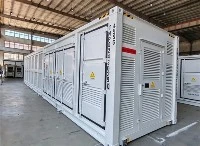
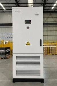
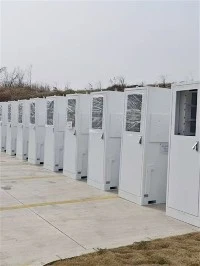
500KW/1MW 1MWh/2MWh Battery Energy Storage System Container
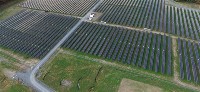
The 500kW/1MW 1MWh/2MWh Battery Energy Storage System Container is a turn‑key utility‑grade energy storage solution housed in standard 20ft or 40ft shipping containers, integrating bidirectional PCS, A‑grade LiFePO4 battery clusters, master BMS, liquid‑cooled thermal management, gas fire suppression, high‑voltage distribution and EMS energy management system with full factory pre‑assembly and pre‑commissioning. Requiring only foundation construction and high‑voltage cable connection for on‑site commissioning, it supports flexible power‑capacity configuration and multi‑container parallel expansion, delivering core capabilities of peak‑shaving and load shifting, renewable energy smoothing, frequency‑voltage grid support, islanded micro‑grid operation and large‑scale emergency backup. Featuring IP54 enclosure protection and comprehensive multi‑layer safety mechanisms, it adapts to diverse harsh outdoor environments, and is widely deployed for ground‑mounted PV power stations, industrial parks, mining operations, island microgrids and grid‑side auxiliary service projects to stabilize grid fluctuations, boost renewable energy utilization and reduce comprehensive energy costs.