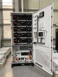
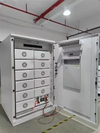
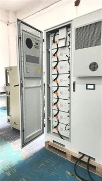
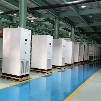
The overall architecture of a commercial and industrial (C&I) energy storage system consists of four major modules: the DC‑side battery system together with the Battery Management System (BMS); the AC‑side Power Conversion System (PCS) plus step‑up transformer; the Energy Management System (EMS) for intelligent energy dispatch; and auxiliary systems including air‑conditioning, fire protection, remote monitoring and alarm units.
Unlike large‑scale centralized energy‑storage power stations that adopt a separated layout for PCS and battery hardware, C&I energy storage widely uses integrated cabinet designs. Thanks to its highly integrated structure, such systems differ significantly from large utility‑scale storage stations in system control logic, refined scheduling and EMS function management, placing higher demands on system‑integration optimisation capabilities.
Peak‑valley tariff arbitrage represents the core and most mainstream revenue model for today's C&I energy‑storage deployments. Energy losses are inevitable during bidirectional power conversion and cyclic dispatch. The industry generally applies the charge‑discharge energy ratio - namely overall system round‑trip efficiency - as the key metric for evaluating the economics of C&I energy‑storage projects and judging product performance.
At present, an overall system efficiency of 90 % has become an implicit technical threshold for premium‑grade C&I energy‑storage products. Industry competition has evolved from simple hardware‑spec comparison toward fine‑tuning of system‑level efficiency. This drives system integrators to continuously reduce full‑machine losses, boost conversion efficiency and maximise peak‑valley arbitrage returns for end users.
How can the industry bottleneck be broken to achieve ultra‑high system round‑trip efficiency above 90 %?
Total energy‑storage‑system efficiency is jointly determined by three core dimensions: DC‑side losses, AC‑side losses, and auxiliary‑equipment power consumption. Starting from system architecture, we break down the technical logic behind high‑efficiency performance layer by layer.
I. DC‑Side Efficiency: Low Internal Resistance as the Fundamental Foundation
The DC‑side system comprises electrical components such as battery cells, aluminium busbars, copper busbars, high‑ and low‑voltage terminals, high‑voltage cables, Manual Service Disconnect (MSD), relays and circuit breakers. Among these items, cell internal resistance is the decisive factor governing DC‑side energy dissipation: lower internal resistance generates less heat loss and delivers superior efficiency.
Modern mainstream 280 Ah large‑capacity cells reach 96 % single‑cell conversion efficiency. After accounting for ohmic heating losses across aluminium busbars, copper busbars, cables, terminals and welding points, mature designs can stabilise DC‑side overall efficiency above 94 %.
To push efficiency further upward, multiple optimisation measures must be implemented: deploying cells with even lower internal resistance, increasing current‑carrying cross‑section of copper busbars and cables, optimising welding procedures and terminal contact structures, and minimising contact impedance and line losses. Such improvements can lift overall DC‑side efficiency beyond 95 %.
II. AC‑Side Efficiency: Topology Upgrade to Cut Conversion Losses
The core AC‑side device is the bidirectional PCS converter. Step‑up transformers are generally unnecessary for 400 V low‑voltage grid‑tied applications, yet mandatory for high‑voltage grid‑connection at 10 kV and above. Excluding transformer losses, power semiconductor switching losses within the PCS constitute the main source of AC‑side energy dissipation.
Premium industry solutions commonly deploy a hardware combination of three‑level topology, IGBTs and SiC diodes. This configuration raises single‑direction AC‑DC / DC‑AC conversion efficiency above 98.5 %. For a complete charge‑discharge cycle (AC‑to‑AC), overall AC‑side conversion efficiency can steadily exceed 97 %.
III. Auxiliary‑System Efficiency: Precision Power‑Consumption Control as a Critical Bottleneck
Equipment including air‑conditioning / liquid‑cooling thermal management units, BMS, EMS, fire‑safety hardware, monitoring modules and auxiliary power supplies draw continuous static power throughout system operation. Thermal‑control hardware accounts for the largest share of auxiliary consumption.
Under high‑temperature summer conditions, air‑conditioning or liquid‑cooling systems often run at full load, introducing fixed energy losses of 3 %‑5 %. Improper component selection or insufficient thermal‑design margins can enlarge these losses further. Leading‑industry specifications require auxiliary‑system power draw to be strictly kept below 5 %.
Breakdown of Real‑World Industry Efficiency Performance
Using current mainstream technical parameters for standardised calculation:
DC‑side efficiency 94 % + AC‑side efficiency 97 % − auxiliary consumption 5 %
Total system round‑trip efficiency = 94 % × 97 % − 5 % = 86.18 %
It follows that most commercially available integrated C&I energy‑storage cabinets deliver real‑world round‑trip efficiency within the 80 %‑88 % range, and generally fail to cross the 90 % premium threshold - representing typical baseline industry performance.
Two distinct product categories exist in today's marketplace:
Products with inflated specifications. Some manufacturers quote only AC‑DC conversion figures while deliberately excluding auxiliary‑system consumption, publishing misleadingly high efficiency claims. Such figures cannot be validated under real operating conditions and severely undermine end‑user economic returns.
Genuine premium high‑efficiency solutions. Through full‑system deep optimisation, DC‑side efficiency rises above 95 %, AC‑side efficiency exceeds 98 %, and auxiliary‑equipment consumption is tightly capped under 3 %. The final full‑machine round‑trip efficiency reaches ≥ 90 %, meeting premium‑tier industry standards.
Products capable of delivering 90 %+ round‑trip efficiency carry substantial technical barriers. They demand strong capabilities in system integration, in‑house hardware development, control‑strategy tuning and full‑scale verification testing. Multiple rounds of commissioning and calibration are required to lock in optimal operating points and minimise end‑to‑end losses.
As energy‑storage hardware and control technologies keep evolving, more high‑performance C&I energy‑storage products will cross the 90 % efficiency threshold. This will drive the industry away from superficial specification competition toward high‑quality development characterised by higher efficiency, greater revenue potential and improved project economics.
125KW 241kWh Battery Energy Storage System Cabinet
The BESS 125KW 241kWh Lithium Battery Energy Storage Cabinet is a high-power, large-capacity integrated energy storage solution engineered for medium-to-large commercial, industrial, and utility-scale applications. It integrates a 125kW high-performance bidirectional inverter, a 241kWh lithium iron phosphate (LiFePO4) battery bank, and a full-featured intelligent energy management system (EMS) into a modular cabinet design. This system enables efficient renewable energy storage, peak shaving, load shifting, grid frequency regulation, and emergency backup power supply. Ideal for large factories, shopping malls, industrial parks, utility-scale solar/wind farms, and microgrids, it enhances energy independence, reduces high grid demand charges, and supports the stable integration of high-penetration renewable energy into the grid.