Case Study: PV‑ESS‑EV Charging Hub With Green‑Power Priority & Smart Sequential Charging For German Highway Service Area

Aug 11, 2026 Leave a message


Project Background


This highway service area is located in Northern Germany, providing fast‑charging service for passenger cars and long‑haul freight vehicles. A 650 kWp solar car‑port PV system is built on‑site. The existing distribution transformer is rated at 630 kVA, maximum stable grid output power limited to 420 kW. The operator planned to deploy eight units of 180 kW DC fast chargers. When all chargers run at full load simultaneously, peak total charging demand reaches 1440 kW, far exceeding original transformer capacity.
 
 
The charging hub operator faced three major practical challenges:


Severe transformer capacity bottleneck. Local DSO requires 12‑24‑month approval procedure for transformer upgrade with high capital investment. Direct activation of all fast chargers will trigger transformer overload and trip‑off, making the station commercially unavailable.


Large fluctuating charging load pushes up energy expenditure. EV arrival concentrates at noon and evening rush hours. Simultaneous high‑power charging creates sharp power spikes, frequently triggering heavy demand‑charge penalty fees. Grid electricity price stays high during daytime, bringing high operational cost if fully powered by utility grid.


Local PV generation cannot be fully utilized. Solar car‑port produces abundant green power in daytime. However, EV arrival is random. Excess solar energy is fed back to grid with very low feed‑in tariff. There is no automatic scheduling logic to make PV energy supply EV charging as first priority.
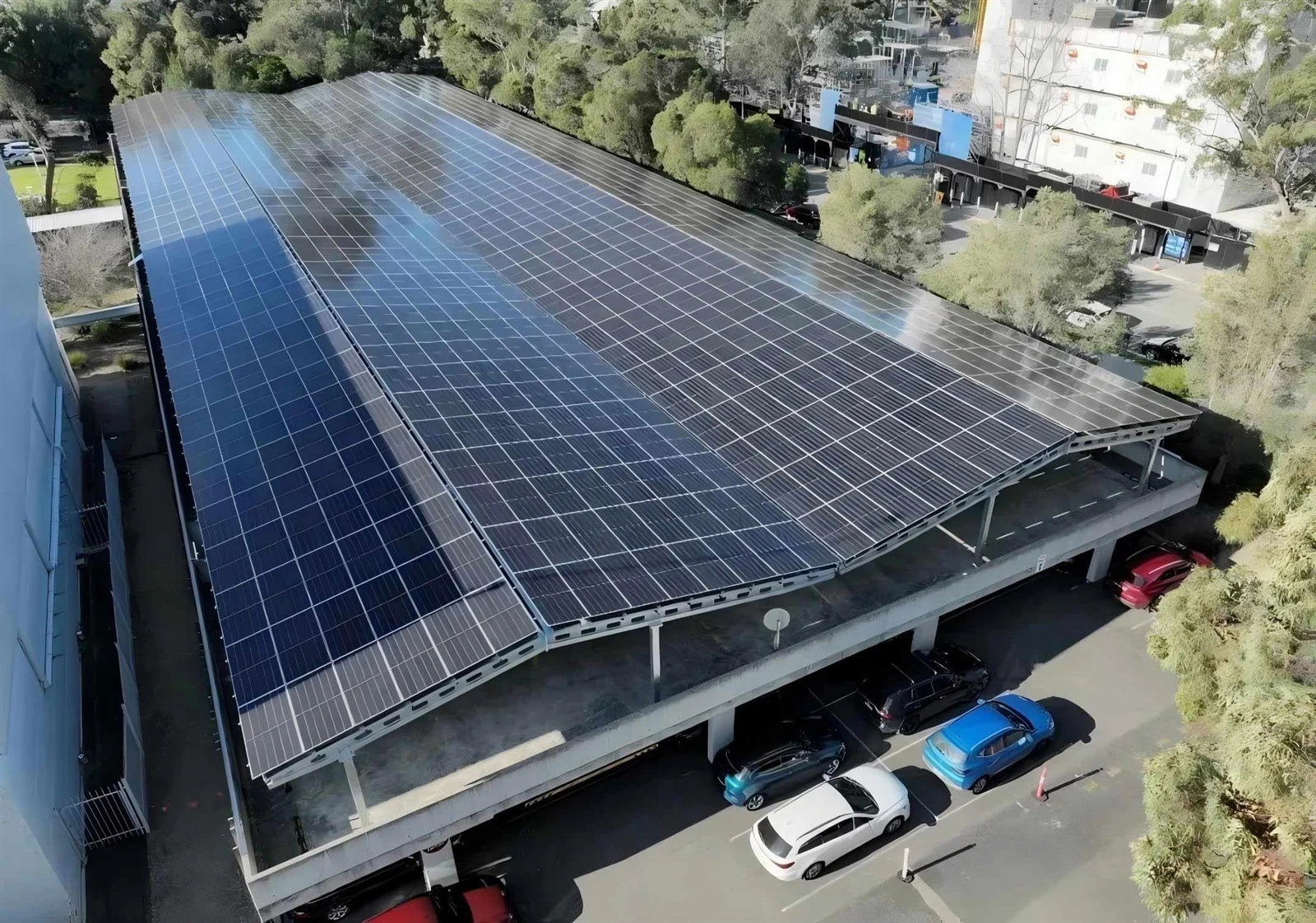
 

Project requirement: Deploy integrated PV‑ESS‑EV charging solution. Keep existing transformer without hardware upgrade, while supporting eight 180 kW DC fast chargers full‑load operation. Realize PV‑priority charging, peak‑shaving via battery energy storage, sequential charging algorithm to mitigate instantaneous power impact. Lower site electricity purchase cost and raise renewable energy consumption ratio, guarantee stable 24‑7 station operation.


EV-car-park


MECC System Solution & Full Equipment List
 
 
Considering onsite 650 kWp PV car‑port, 420 kW grid power limit from transformer and eight 180 kW DC fast chargers, MECC adopted AC‑coupled modular energy‑storage architecture. MECC 125 kW/261 kWh liquid‑cooled PCS cabinets are deployed, together with expandable 1‑2 MWh containerized BESS. Total installed power reaches 750 kW, total usable energy capacity 1566 kWh.


Key equipment includes:


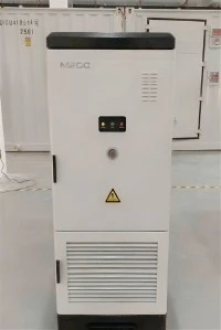
Four units of MECC 125 kW/261 kWh liquid‑cooled PCS energy‑storage cabinets, AC‑coupled to onsite 400 V low‑voltage busbar. Integrated bi‑directional PCS, liquid‑cooled thermal management, aerosol fire suppression and BMS. CE/IEC certified for outdoor installation. Each cabinet provides 125 kW /261 kWh, total 500 kW /1044 kWh for four cabinets, undertaking core peak‑shaving, short‑term power support and off‑peak grid‑charging tasks.


One set of MECC 1‑2 MWh grade containerized energy‑storage system. Phase‑1 configuration delivers 250 kW /522 kWh for power and energy supplement. Pre‑reserved expansion interfaces support future upgrade up to full 2 MWh when EV traffic grows. Inside container are integrated power‑distribution unit, liquid‑cooled thermal control, fire‑protection system and complete earthing protection, adapted to wide outdoor temperature range in Europe.


One set of MECC‑EMS PV‑ESS‑charging dedicated industrial energy‑management platform with local edge unit and cloud backend, acting as core dispatching brain of whole charging hub. It connects PV inverters, parallel PCS clusters, eight DC fast chargers and main grid‑incoming meter. Embedded AI‑driven EV‑traffic and PV‑output forecasting algorithm implements full logics: PV‑priority charging strategy, ESS peak‑valley optimization, sequential charging load management. Time‑of‑use tariff configuration, operational report generation and cloud remote monitoring are supported. Local edge controller maintains full control logics even under cloud‑network disconnection.


One unit of MECC ACCU‑200 micro‑grid coordination controller, millisecond‑level real‑time control hardware. It monitors grid power limit, sends charge‑discharge commands to energy‑storage system, and delivers power‑adjustment instructions to chargers for sequential charging. It strictly limits maximum power drawn from grid below transformer safety threshold of 420 kW to avoid transformer overload.


Multiple sets of high‑precision sensing assemblies including CT current transformers and multi‑function smart meters. Installed at transformer main incoming point, PV PCC point, ESS AC combiner cabinet and charger power distribution cabinet. Millisecond‑level acquisition for grid power, real‑time PV generation, battery SOC and real‑time power consumption of each charger, providing raw measurement data for all control algorithms.


One set of PV AC combiner cabinet, receiving AC output from 650 kWp PV car‑port inverters, performing AC power collection, surge protection and over‑current protection before connecting to onsite 400 V busbar.


One set of PV‑ESS‑charging AC grid‑connection combiner cabinet, equipped with circuit‑breaker, secondary surge protection and hardware overload protection device. It realizes power combination for liquid‑cooled cabinets, container BESS, PV system, EV chargers and utility grid. Hardware overload relay provides fail‑safe backup against software failure, together with EPO emergency shutdown interface.


One set of communication assembly including industrial Ethernet switch, 4G‑wired dual‑link and super‑capacitor backup power source. It guarantees stable communication among EMS, coordination controller, PCS, BMS, PV inverters and smart EV chargers, preventing scheduling failure caused by network fluctuation.


Eight third‑party 180 kW intelligent DC fast chargers, supporting remote power adjustment and receiving power commands from EMS to cooperate with sequential charging logic.


Core Technical Principles


1. PV‑priority for EV charging


EMS reads real‑time output of PV inverters. Solar power supplies EV charging with highest priority. When PV generation can fully cover charging demand, EVs are 100% powered by on‑site PV without grid import. If PV output exceeds total EV charging load, surplus solar power charges battery energy storage system. When PV generation drops insufficient, battery discharges first to compensate power gap. Only when battery SOC is low, additional power is imported from utility grid. This logic maximizes on‑site PV self‑consumption and minimizes grid feed‑in.


2. Energy‑storage peak shaving and valley filling


Hard grid‑power limit is set at 420 kW according to transformer rating. When multiple EVs start fast‑charging simultaneously and total charging load exceeds 420 kW, all excess power demand is instantly supplemented by energy‑storage discharge. Therefore the charging hub can deliver far higher instantaneous power without transformer upgrade. During night off‑peak hours with low electricity tariff, batteries are charged from grid when few EVs present. In high‑price daytime periods, stored energy is discharged for EV charging to realize peak‑valley arbitrage and cut operational expenditure.


3. Sequential charging control to prevent transformer overload


Coordination controller continuously monitors real‑time power at transformer incoming point. Total power imported from grid is strictly capped under 420 kW.


If aggregated EV charging demand exceeds sum of grid allowable power plus maximum ESS discharge capability, EMS will flexibly derate partial charger output and redistribute available power among connected EVs instead of cutting off charging session directly. Power allocation considers EV connection time and remaining charging energy requirement, keeping transformer running within safe load range and eliminating trip‑off risk. Hardware overload relay in AC combiner cabinet works as final fail‑safe protection against communication failure.


Closed‑loop energy‑flow logic


‑ Daytime high irradiation: PV → supply EV charging first → surplus energy charges battery;
‑ Insufficient PV output: Battery discharges to fill power gap → import grid power only at low SOC;
‑ Charging peak spike: Grid provides base 420 kW, battery covers remaining power gap;
‑ Night‑time off‑peak: Battery charges from grid at low tariff in preparation for next‑day peak demand;
‑ Over‑demand scenario: Trigger sequential charging and smooth power derating to avoid transformer overload.


Commissioning & Operational Results


After installation, commissioning and grid‑connection, the PV‑ESS‑charging hub goes into commercial operation. Eight 180 kW fast chargers run fully with original 630 kVA transformer without any hardware modification.


1.Successful commercial launch without transformer upgrade. Maximum grid import is firmly limited under 420 kW. High‑power simultaneous EV charging is supported by battery discharge. Expensive transformer reconstruction and long approval waiting period are avoided.


2.Noticeable operational cost reduction. Combined benefit of off‑peak battery charging and PV self‑consumption reduces monthly grid power purchase volume by 33%. Demand‑charge penalty risk is fully eliminated, lowering per‑kWh charging cost.


3.Greatly improved renewable energy self‑consumption ratio. PV self‑consumption rate rises from original 47% up to 86%. Large share of solar energy directly powers EV charging and realizes low‑carbon operation for highway service area.


4.Stable sequential‑charging performance. During rush‑hour heavy EV arrival, system automatically redistributes power flexibly. Transformer overload never occurs, all connected vehicles keep charging without abrupt interruption and guarantee good end‑user experience.


Project Significance & Industry Demonstration Value


This real‑world German highway‑service‑area case fully validates three core strategies for PV‑ESS‑charging scenario: PV‑priority charging, energy‑storage peak‑shaving and sequential overload‑protection charging. Based on modular combination of MECC 125 kW/261 kWh liquid‑cooled PCS cabinets and expandable 1‑2 MWh containerized BESS, the solution can be flexibly scaled for highway service stations, industrial‑park charging depots and remote campsites.
 
 
Numerous existing charging hubs across Europe face transformer bottleneck with expensive and time‑consuming grid reinforcement. This project proves that integrated PV‑ESS‑charging architecture enables high‑power fast‑charging deployment without distribution‑network upgrade. It solves hardware challenges of transformer overload and violent charging power spikes. Meanwhile it reduces operational electricity cost and lifts renewable energy penetration, delivering replicable reference for similar European charging‑station projects.


Related Products


Liquid Cooling 125KW 261kWh Lithium Battery Energy Storage Cabinet


The IP55 Protected All-in-One Solar Energy Storage Cabinet is a high-performance, integrated energy solution engineered for outdoor commercial, industrial, and utility-scale solar applications. It integrates a 125kW Power Conversion System (PCS), a 261kWh lithium iron phosphate (LiFePO4) battery bank, an advanced liquid cooling system, and a intelligent Battery Management System (BMS) into a single cabinet with IP55 weatherproof protection. Designed to withstand harsh outdoor environments while delivering efficient energy conversion and storage, it supports solar energy absorption, peak shaving, load shifting, grid auxiliary services, and emergency backup power. Ideal for utility-scale solar farms, industrial parks, large commercial complexes, and remote microgrids, it provides a reliable, space-saving, and low-maintenance solution for large-scale renewable energy integration.

page-1000-1000


Send Inquiry

whatsapp

Phone

E-mail

Inquiry