


Before a single battery energy storage system (BESS) is installed, it exists as a drawing: the single-line diagram. Often called an SLD or one-line diagram, it is the master schematic showing how every major component - from utility service to battery to loads - connects and where protection sits. Engineers design from it, utilities review it, and contractors build to it. Buyers who learn to read one avoid the change orders that quietly inflate a commercial energy storage project by double digits.
What a single-line diagram actually is
An SLD represents an electrical system with single lines and standard symbols rather than physical layouts. It shows how power flows, where it converts (AC to DC and back), and where it is protected - but not where each box sits on the pad. For an ESS, the SLD is the authoritative document for scope, protection, and interconnection. When engineers say "it's on the one-line," this is what they mean.
Why buyers - not just engineers - should care
The SLD is where project cost lives. It defines whether you need a new transformer, an upgraded switchgear, additional protection relays, and where the point of common coupling (PCC) sits. A quote based on a clear SLD is trustworthy; a quote based on a verbal scope hides risk. Reading the SLD - or at least asking the right questions about it - lets you compare commercial energy storage cost per kWh across vendors on equal footing, rather than discovering hidden scope later.
Core elements of an ESS single-line diagram
A typical C&I battery storage SLD includes:
Utility service and metering, ending at the PCC where the site connects to the grid.
Main switchgear and transformer, with the breakers and disconnects that isolate the system.
Solar generation (if present): combiners and inverters feeding the AC bus - the heart of commercial solar plus storage.
Battery section: modules, the BMS (battery management system), and the PCS (power conversion system).
AC or DC bus showing the coupling arrangement.
Loads, including a highlighted critical load panel if the site wants backup.
Protective devices, grounding, metering, and the EMS (energy management system) communications path.
Every one of these blocks carries cost and code implications.
Where coupling shows up on the diagram
AC-coupled and DC-coupled systems look different on the one-line. AC coupling shows the battery's PCS landing on the AC bus beside the PV inverter; DC coupling shows PV and battery sharing a DC bus behind a single hybrid inverter. The choice changes protection requirements, round-trip efficiency, and how the system islands - so the SLD is where the architecture debate gets concrete.
Protection and safety on the drawing
The SLD is a safety document. It must show circuit breakers, fuses, DC disconnects, ground-fault protection, and anti-islanding relaying (per interconnection rules such as IEEE 1547) so the system never back-feeds a dead grid. Fire-safety interfaces appear here too, because NFPA 855 governs spacing and protection while UL 9540 and UL 9540A cover system and fire testing; IEC 62619 applies to international cells. A clean SLD makes compliance review fast; a sloppy one invites delays.
Interconnection and utility review
Utilities approve projects by reviewing the SLD against their interconnection requirements at the PCC. Missing or mislabeled protection can stall approval for weeks. Whether the project supports peak shaving, TOU arbitrage, demand response, or a microgrid, the diagram must clearly define the export path and its limits.
Common SLD mistakes that cost money
Recurring problems include:
Undersized transformer or switchgear, forcing an upgrade mid-project.
Missing protection that fails utility review.
Ambiguous scope - unclear who supplies the disconnect or meter.
No communications path for the BMS, PCS, and EMS, complicating commissioning.
Ignoring future expansion for modular energy storage or added EV charging capacity.
Each becomes a change order if the SLD wasn't done right the first time.
From drawing to dollars
An accurate SLD is the basis for real economics. With scope clear, vendors can quote LCOS (levelized cost of storage), battery storage ROI, and commercial battery storage payback honestly, and designers can size C-rate and duration correctly using a 215 kWh battery storage module or all-in-one energy storage cabinet. Conversely, a vague diagram produces vague numbers - and vaporized savings.
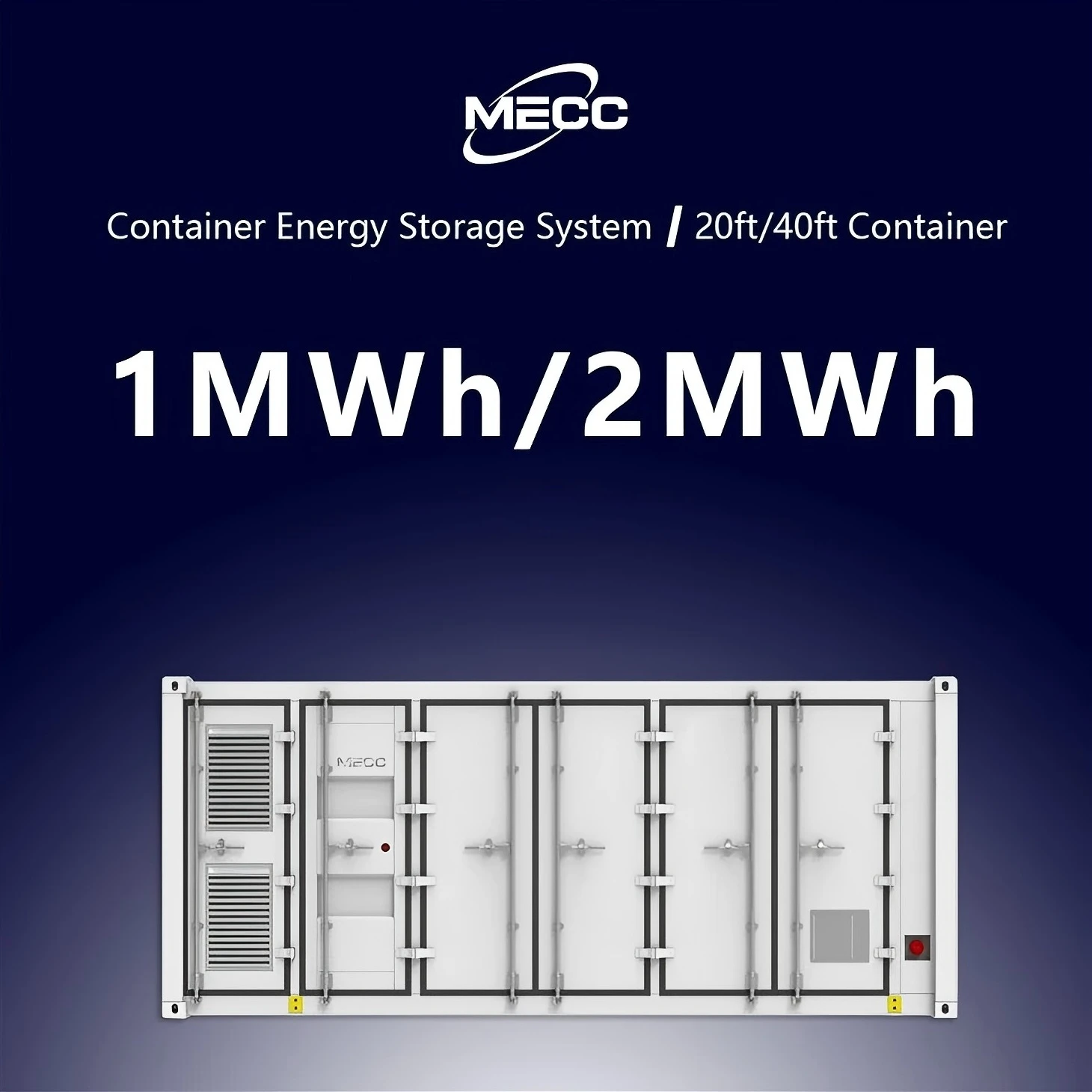
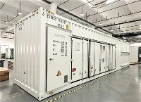
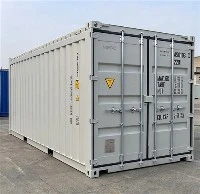
500KW/1MW 1MWh/2MWh Battery Energy Storage System Container
The 500kW/1MW 1MWh/2MWh Battery Energy Storage System Container is a turn‑key utility‑grade energy storage solution housed in standard 20ft or 40ft shipping containers, integrating bidirectional PCS, A‑grade LiFePO4 battery clusters, master BMS, liquid‑cooled thermal management, gas fire suppression, high‑voltage distribution and EMS energy management system with full factory pre‑assembly and pre‑commissioning. Requiring only foundation construction and high‑voltage cable connection for on‑site commissioning, it supports flexible power‑capacity configuration and multi‑container parallel expansion, delivering core capabilities of peak‑shaving and load shifting, renewable energy smoothing, frequency‑voltage grid support, islanded micro‑grid operation and large‑scale emergency backup. Featuring IP54 enclosure protection and comprehensive multi‑layer safety mechanisms, it adapts to diverse harsh outdoor environments, and is widely deployed for ground‑mounted PV power stations, industrial parks, mining operations, island microgrids and grid‑side auxiliary service projects to stabilize grid fluctuations, boost renewable energy utilization and reduce comprehensive energy costs.