


1. Introduction to LFP Prismatic Cells
1.1 Basic Structure of Lithium-Ion Batteries
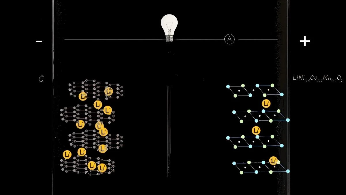
Lithium-ion batteries consist of several core components, each serving a critical function in the energy storage and transfer process:
Cathode Material: Utilizes layered lithium metal oxides (e.g., LiCoO2, NCM) or olivine structures (e.g., LiFePO4), providing storage space for lithium ions.
Anode Material: Typically graphite; new materials include silicon-based composites that break the capacity limits of traditional graphite.
Electrolyte: Liquid electrolytes (e.g., LiPF6 dissolved in carbonate solvents) or solid-state electrolytes (e.g., sulfide glass-ceramics) responsible for lithium-ion transport.
Separator: Microporous polypropylene (PP) or ceramic-coated materials that provide electronic insulation while allowing ion conduction.
Current Collector: Aluminum foil is commonly used for the cathode, and copper foil for the anode.
1.2 Prismatic Cell Architecture
Lithium Iron Phosphate (LFP) cells are preferred for their excellent thermal stability (thermal runaway temperature typically > 260°C).
The internal structure of prismatic cells is usually constructed using one of two processes:
Wound Jelly Roll: A mature technology with efficient manufacturing, where the electrode layers are wound around a vertical axis.
Stacking Process: Offers higher space utilization, energy density, and lower internal resistance, but involves a more complex manufacturing process with higher risks of internal short circuits.

2. Overview of High-Temperature Damage Mechanisms
2.1 Cathode Structural Degradation
High temperatures trigger three primary degradation modes in the cathode:
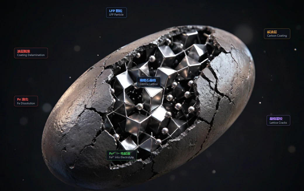
Fe2+ Dissolution: HF corrosion of LFP particles causes Fe2+ to dissolve into the electrolyte, migrate to the anode, and deposit on the SEI, destroying its structure.
Carbon Coating Degradation: Delamination of the carbon coating occurs at temperatures > 60°C due to volume changes (~6.8%), leading to conductive network disconnection and irreversible capacity loss.
Lattice Stress Cracking: Non-uniform delithiation rates at high temperatures create concentration gradients and mechanical stress at phase boundaries, causing cracks to propagate from the surface to the interior.
2.2 Anode Degradation & Lithium Plating
The graphite anode faces threats from solvent co-intercalation, particle cracking (volume change ~10%), and staging feature degradation.
Lithium Plating (Li+ + e- -> Li0) is a critical concern. While often considered a 'low-temperature' issue, high temperatures also accelerate lithium plating due to uneven current density and SEI thickening, which increases diffusion resistance. Hazards include dendrite growth and increased internal resistance.

2.3 SEI Decomposition & Regrowth Cycle
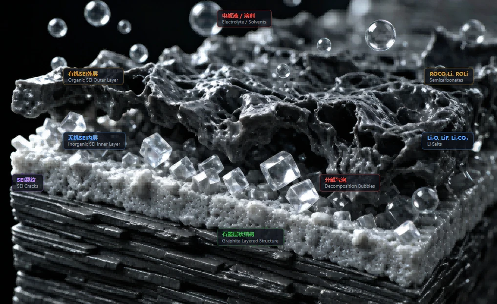
The SEI (Solid Electrolyte Interphase) has a double-layer structure: an inorganic inner layer (Li2O, LiF) and an organic outer layer (ROCO2Li, ROLi).
At temperatures > 45°C, a cycle of 'Decomposition -> Exposure -> Regeneration' occurs. Each cycle irreversibly consumes active lithium (LLI) and releases gases (C2H4, CO2), leading to capacity decay and internal pressure increase (swelling).
2.4 Electrolyte Decomposition & Gas Generation
Carbonate solvents (EC/DMC) undergo decarboxylation at high temperatures, producing gases such as CO2, C2H4, and CO. CO2 is the primary component of the generated gas.

2.5 LiPF6 Decomposition & HF Corrosion
LiPF6, the most common lithium salt, has limited thermal stability and begins to decompose > 55°C. This produces PF5, which reacts with trace amounts of water to form HF (Hydrofluoric Acid). HF acts as a catalyst for material degradation, attacking the cathode particles, the aluminum current collector, and the PVDF binder.
3. Mechanism Coupling & Improvements
3.1 Mechanism Coupling & Positive Feedback Loops
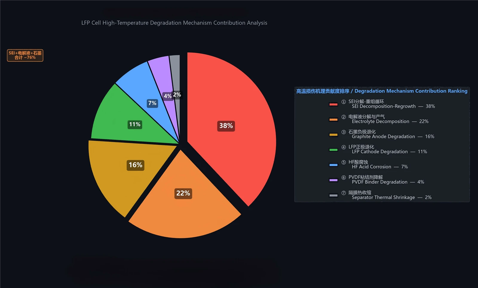
High-temperature damage is not the result of independent mechanisms but a coupled process forming positive feedback loops:
SEI Chain Reaction: Decomposition leading to new SEI formation, increasing impedance and generating more heat.
HF Corrosion Cascade: LiPF6 decomposition producing HF, which causes Fe dissolution and SEI destruction, further accelerating electrolyte decomposition.
Lithium Plating Cycle: High charge rates at high temperatures leading to lithium plating, which reacts with the electrolyte to generate more heat.
3.2 Macroscopic Parameter Changes
|
Parameter |
Change |
Typical Range |
Dominant Micro-mechanism |
|
Capacity |
Decay (↓) |
20-40% decay (45°C, 1000 cycles) |
Active lithium consumption + Particle insulation |
|
DCR (Internal Resistance) |
Increase (↑) |
50-150% increase (45°C, 1000 cycles) |
SEI thickening + Al foil corrosion + Binder failure |
|
Thickness |
Swelling (↑) |
5-15% increase (45°C, 1000 cycles) |
Gas generation + SEI accumulation + Graphite delamination |
|
Self-discharge Rate |
Increase (↑) |
3-5 times higher than room temp |
Fe2+ migration + SEI defects + Micro-shorts |
|
Cycle Life |
Shorten (↓) |
Reduced to 1/3 - 1/2 of 25°C baseline |
Accumulation of all mechanisms |
|
Coulombic Efficiency |
Decrease (↓) |
99.9% -> 98-99% |
Irreversible side reactions + Lithium plating |
|
Gas Generation |
Surge (↑) |
5-10 times higher than room temp |
EC/DMC decomposition + SEI decomposition |
3.3 Engineering Improvement Directions
Key strategies for improving high-temperature performance include:
Electrolyte Optimization: Adding FEC/VC to build a denser, stable SEI, or replacing LiPF6 with LiFSI.
Electrode & Material Optimization: Applying oxide coatings (Al2O3/ZrO2) to LFP particles and implementing graphite surface treatments.
System-level Thermal Management: Strictly controlling the working temperature below 40°C. Reducing temperature by 5°C can improve cycle life by 30-50%.