


Selection of energy storage solutions
At present, the energy storage technologies with high technological maturity and wide application are pumped storage and electrochemical energy storage. Electrochemical energy storage mainly utilizes lithium battery technology. Considering factors such as cost-effectiveness, safety, service life, and industry maturity, lithium iron phosphate batteries are currently the most suitable batteries for energy storage. Thermal power energy storage assisted frequency regulation has high requirements for the performance of energy storage batteries, including high rate characteristics, high climbing characteristics, fast response capability, strong energy efficiency ratio, high temperature safety, and long life of energy storage technology. Therefore, for thermal power energy storage combined frequency regulation projects, it is recommended to use lithium iron phosphate batteries. From the perspective of user side energy storage application scenarios, it is also recommended to use lithium iron phosphate batteries based on requirements such as peak shaving, demand response, and power supply reliability.
Battery fires are mainly caused by thermal runaway of the battery, which is mainly due to internal short circuits. The main causes of internal short circuits include mechanical abuse, electrical abuse, and thermal abuse. The way to deal with thermal abuse is to adopt good thermal management design.
Liquid cooling technology uses liquid convection heat transfer to remove the heat generated by the battery and reduce its temperature. The risk of liquid leakage in liquid cooling can be avoided through structural design. The efficiency of liquid cooling is higher than that of air cooling, and the temperature difference control of liquid cooling is better than that of air cooling. The fluid temperature and flow control of liquid cooling is simpler than that of air cooling, and the battery life using liquid cooling is longer. Considering the overall cost, liquid cooling systems have more advantages than air cooling systems. At the same time, safety issues in energy storage power plants are prominent, and liquid cooling energy storage systems are gradually being promoted and applied.
Liquid cooled lithium battery energy storage system
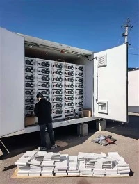
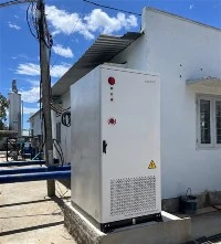
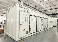
The lithium battery energy storage system consists of a battery compartment and an electrical compartment. The battery compartment is composed of battery clusters, liquid cooling systems, fire protection systems, combiner cabinets, distribution boxes, etc. The electrical compartment is composed of inverters (PCS), transformers, control cabinets, ring main units, AC distribution cabinets, air conditioning, etc. This study provides a detailed description of the design and development of the battery compartment, while the description of the electrical compartment is omitted. The entire design process of lithium battery energy storage system includes battery pack, battery rack, and battery container, as shown in the figure.

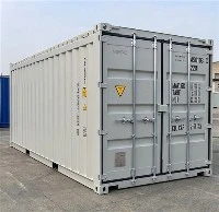
The energy storage system uses EVE Energy square aluminum shell lithium iron phosphate LF280K battery cells (3.2 V/280 Ah). The series parallel connection of the battery pack is 1P48S, and each battery pack has 48 LF280K battery cells with a capacity of 43.008 kW · h. The battery system consists of 8 battery clusters connected in parallel, with each cluster consisting of 8 battery packs connected in series. The energy storage system has a capacity of 2.75 MW · h and a rated voltage of 1228.8 V. The energy storage system battery compartment is a standard 20 foot high container (6.058 m x 2.438 m x 2.896 m) with functions such as waterproofing, insulation, corrosion prevention, fire prevention, sand blocking, shock resistance, and UV protection. Its protection level is IP54. In order to prevent overcharging and overdischarging of batteries, achieve charge and discharge management of batteries, and ensure stable and reliable operation of the battery system, the system must be equipped with a Battery Management System (BMS), and protective hardware must be equipped with relays, circuit breakers, fuses, etc.
Energy storage thermal management design
Design of Thermal Management System
The liquid cooling and heating management system consists of liquid cooling plates, liquid cooling units, liquid cooling pipelines, high and low voltage wiring harnesses, and coolant. Regarding the issue of liquid cooling leakage, the following measures are taken. Firstly, the liquid cooling joint adopts a car grade leak proof cooling pipeline quick plug joint, which can ensure that the risk of liquid leakage is minimized during the operation of the energy storage system. Secondly, a liquid level sensor should be installed in the expansion tank of the liquid cooling unit. If there is any leakage, the liquid cooling unit will sound an alarm. Thirdly, the protection level of the battery pack design is IP67, ensuring that there is no impact on the system in case of leakage. The liquid cooling plate of the battery pack is made of aluminum alloy die-casting and integrated with the functions of the base and liquid cooling plate. The liquid cooling plate and the sealing cover plate are connected by friction stir welding; At the same time, the liquid cooling plate will also undergo airtightness testing to ensure good sealing performance. The battery pack liquid cooling plate adopts a "serpentine" flow channel, and the coolant uses 50% water by mass and 50% ethylene glycol by mass. The liquid cooling system uses a certain thermal management strategy to cool or heat the battery pack when the coolant flows through the liquid cooling plate.
Liquid cooling units have cooling, heating, and dehumidification functions, and the strategy and working mode of the thermal management system for liquid cooling units are closely related. In the text, Tmax refers to the highest temperature of the battery; Tvag refers to the average temperature of the battery; Tmin refers to the lowest temperature of the battery.
When Tmax ≥ 28 ℃ and Tvag ≥ 25 ℃, the liquid cooling unit enters the refrigeration mode, the compressor is turned on, and the high-temperature and high-pressure refrigerant is discharged from the compressor and enters the condenser for condensation. After releasing heat and cooling, it is throttled and depressurized through the expansion valve, and then enters the evaporator to exchange heat with the coolant. The refrigerant absorbs heat and evaporates in the evaporator before flowing back to the compressor suction port, completing a refrigeration cycle. At this time, the water pump in the waterway is turned on, the PTC heater is not turned on, and the coolant is cooled in the plate evaporator and enters the battery pack liquid cooling plate to cool the battery and remove heat, thereby achieving the purpose of cooling the battery. When Tmax ≤ 25 ℃ and Tvag ≤ 22 ℃, stop the cooling mode.
When Tmin ≤ 12 ℃ and Tvag ≤ 15 ℃, the liquid cooling unit enters heating mode, the compressor is turned off, the water pump and PTC heater are turned on, and the coolant is heated by the PTC heater and enters the battery cooling plate to heat the battery. This mode is suitable for situations where the battery temperature is too low and heating is required. Stop heating mode when Tmin ≥ 20 ℃ and Tvag ≥ 23 ℃.
When the inlet temperature is ≤ 12 ℃, the liquid cooling unit enters self circulation mode, the compressor, fan, PTC heater are turned off, and the water pump is turned on, allowing the coolant to circulate repeatedly in the battery cooling plate and the unit, carrying out the heat in the battery pack. When the humidity inside the container is higher than the dew point temperature at the corresponding temperature, the liquid cooling unit will activate the dehumidification mode.

Energy storage fire protection system
The fire protection system uses each battery pack as the minimum protection unit and adopts a new fire extinguishing technology solution of gas-liquid two-phase atomized fire extinguishing agent. It jointly uses suction detectors, combustible gas detectors, and temperature and smoke detectors to comprehensively monitor and detect the entire energy storage box in real-time. Among them, the inspiratory detector monitors and protects the entire cluster battery box in units of battery clusters, the combustible gas detector monitors and protects the batteries, and the temperature and smoke detector monitors and protects the electrical compartment.
When a battery pack experiences a thermal runaway fire, the detector detects the fire and opens the partition control valve of the battery cluster. At the same time, the fire information is transmitted to the fire suppression host through the CAN bus. The sound and light alarm is turned on, the exhaust system is turned on, and the suppression host starts to output. The fire extinguishing agent is transported to the gas-liquid two-phase nozzle through the pipeline and partition control valve. The fire extinguishing agent is atomized through the nozzle and then sprayed into the interior of the battery pack to implement cooling and fire extinguishing functions.
The energy storage fire suppression host uses perfluorohexane as the main fire extinguishing agent to extinguish, suppress, and prevent early fires in the energy storage cabinet. Once the fire is too large, the fire extinguishing agent needs to be sprayed for a long time. After the built-in perfluorohexane fire extinguishing agent in the host is used up, the system will automatically replenish the fire hydrant water to achieve long-term continuous spraying, suppress fire reignition, and cool down the battery.

Test verification
The liquid cooled container energy storage system undergoes a 0.5C charging test at an ambient temperature of 25 ℃, and the BMS records the temperature changes of each battery pack. At the end of charging, the surface temperature of the battery cells inside the battery pack is less than 35 ℃, with a temperature rise of less than 10 ℃. Throughout the entire charging process, the lowest temperature at the monitoring point is 32.5 ℃, and the highest temperature is 34.8 ℃, with a temperature difference of less than 2.3 ℃, as shown in Figure 2. From the experimental results in Figure 2, it can be seen that the temperature rise of liquid cooled containers is much smaller than the temperature difference of air-cooled containers. Generally, the temperature difference of air-cooled containers reaches 5-8 ℃, which can effectively promote the temperature consistency of the entire energy storage system and extend the system's operating life.

Conclusion
The project designed a 20 foot liquid cooled container energy storage system, including system theoretical design, thermal management design, fire protection design, etc. Finally, experimental verification showed that the temperature consistency of the energy storage system was good and the temperature rise met the requirements.
The use of liquid cooled battery packs in new energy vehicles is very mature, and the energy storage system is stationary without the risk of leakage. The liquid cooled container system reduces the design of internal air ducts, adopts an external maintenance system, eliminates the need for internal corridor space, and adopts a large battery pack design to maximize energy density. In terms of overall cost, the liquid cooled container energy storage system has more advantages. The most important thing for the energy storage system is to ensure its safety, and the design of the fire protection system is crucial. The system adopts Pack level fire protection and a continuous suppression scheme of perfluorohexane and water fire protection to ensure the safe operation of the system.