





A site adds EV chargers, replaces gas heating with heat pumps, installs a new production line - and the transformer that was comfortable at 60% loading is suddenly at 95% for two hours a day. The utility quote arrives: a larger transformer, new switchgear, a service interruption, and eighteen months.
Transformer upgrade deferral with a battery is the alternative. Cap the site's import below the existing rating, let the battery carry the difference during peaks, and postpone the capital project. Done well, it buys years. Done badly, it buys a battery that cannot recharge because the site has no headroom left.
This article sets out the engineering, the economics, and the traps.
Two different deferral problems
The term is used for two distinct situations, and they have different rules.
Utility-side deferral. A distribution utility defers a substation or feeder upgrade by contracting storage or demand response on the network. This is a non-wires alternative, governed by the utility's planning process, procurement rules and often a regulated agreement. The customer is a participant, not the asset owner.
Customer-side deferral. A site owner defers upgrading its own service transformer, switchgear or utility connection. The constraint is the rating of equipment serving the site, and the battery sits behind the meter.
This article is about the second case, which is what most C&I buyers actually face. The first is worth knowing about because in some markets the utility will pay for part of the battery if it also solves a network constraint - a double value stream worth asking about.,
The constraint is thermal, not instantaneous
A transformer's nameplate rating is a continuous thermal rating at a defined ambient and temperature rise. It is not a hard instantaneous limit.
IEEE C57.91 and equivalent standards describe loading beyond nameplate with predictable effects: a transformer can carry 110–125% for hours under favourable ambient and prior loading, at the cost of accelerated insulation ageing. Short peaks matter less than sustained overload, because the winding has thermal inertia.
Three practical consequences:
The design basis should be the thermal duty, not a single peak value. A 15-minute excursion to 110% may be entirely acceptable; three hours at 105% every day is a different matter.
You can bank some deferral on cyclic loading. But you are spending insulation life, and the asset owner must accept that explicitly. Do not let a vendor assume it silently.
The billing constraint may be stricter than the thermal one. If the tariff has a ratchet or a contract demand, the commercial limit may bind before the transformer does. Design to the tighter of the two.
For most projects, the simplest and most defensible target is: keep site import at or below nameplate kVA, with a small margin for metering error and unplanned load.
Rule out the cheap options first
Before sizing a battery, check three things that are almost always cheaper per kVA freed.
Power factor correction. If the site runs at 0.85 power factor, correcting to 0.95 reduces kVA by roughly 10% for the same kW - often for a few thousand dollars of capacitors. If the transformer constraint is kVA, this may defer the upgrade on its own, or significantly shrink the battery.
Load management and scheduling. Moving a chiller charge cycle, staggering motor starts, or sequencing EV charging can shave the peak without hardware. On sites with a few discrete loads, this is often the highest-return measure available.
Managed EV charging. If the growth is chargers, reducing per-session power or staggering sessions may cut the peak by 30–50% with no battery at all.
A battery is the right answer when the load is genuinely uncontrollable, the peak is sharp, and the upgrade is expensive or slow.
How the battery defers the upgrade
The mechanism is straightforward: discharge to hold site import below a setpoint derived from the transformer rating.
The engineering is in four numbers.
1. The firm capacity you are protecting. Transformer rating in kVA, multiplied by the power factor you intend to operate at. A 750 kVA unit at 0.95 PF supports about 712 kW. State the basis.
2. The load at the end of the deferral window. This is the most commonly missed step. If the site grows 8% a year and you want to defer for four years, the battery must cover the gap in year four, not year one. Sizing for year-one load produces a system that runs out of capability exactly when the deferral is supposed to be paying off.
3. The peak gap and its duration. Power equals the difference between expected peak and the cap. Energy equals the area above the cap on the worst days, after efficiency and depth-of-discharge derating - the same calculation as any peak-shaving project.
4. Off-peak headroom for recharging. This is the circularity trap, and it sinks more projects than any other.
The recharge circularity
A battery that discharges 500 kWh must recharge 570 kWh or so, and that charging load flows through the same transformer it is trying to protect.
If the site's overnight load is 600 kW on a 712 kW transformer, headroom is 112 kW. Recharging 570 kWh at 112 kW takes over five hours. That may be feasible. If overnight load is 680 kW, headroom is 32 kW, and recharging takes eighteen hours - the battery will not be ready for the next day's peak.
The check is a daily energy balance:
Energy discharged per day ≤ headroom power × available charging hours
If it fails, the options are: a larger transformer (defeating the purpose), a larger battery with a smaller depth of discharge (more capacity, same throughput limit), managed charging of the battery into windows you create by shifting other loads, or accepting that the battery covers only part of the peak.
Run this calculation on the worst day of the deferral window, not on an average day.
A worked example
A site has a 750 kVA transformer, operates at 0.95 power factor, and currently peaks at 700 kVA. Growth is projected at 7% a year, taking the peak to about 850 kVA in three years. The utility quotes $350,000 and eighteen months for a 1,000 kVA upgrade.
The owner wants to defer for four years.
Target cap: 700 kVA - the current peak, comfortably below the 750 kVA rating.
Year-four peak: 850 kVA. Gap: 150 kVA, or about 143 kW at 0.95 PF.
Power: 150 kW, with a 10% margin for forecast error → 165 kW.
Energy: On the worst days, the load exceeds the cap for about three hours. Area above the cap ≈ 400 kWh delivered.
Divide by 0.88 round-trip efficiency → 455 kWh from the cells.
Divide by 0.90 usable depth of discharge → 505 kWh nameplate.
Add 15% reserve → 580 kWh.
Specification: roughly 165 kW / 580 kWh.
Recharge check: overnight load is 450 kW, so headroom is 250 kW. Recharging 455 kWh takes 1.8 hours, well inside the off-peak window. The balance works.
Economics: $350,000 avoided for four years, against a battery in the region of $180,000–$260,000 installed, depending on market and specification - and the battery continues to deliver demand-charge savings and resilience value after the upgrade eventually happens. That last point is what makes the case to a CFO: unlike a transformer, the battery is not stranded when the deferral ends.
When deferral does not work
Be willing to say no. Five conditions kill the case:
Load grows faster than the battery can follow. If the gap doubles every two years, you will be adding batteries faster than you would have upgraded.
The peak is flat and long. A site that sits at 105% of rating for ten hours a day needs capacity, not a buffer.
There is no off-peak headroom. The circularity check fails and no amount of dispatch logic fixes it.
The transformer is already overloaded continuously. Deferral assumes you can return to normal loading; if the base load alone exceeds rating, storage only shaves the increment.
Space, access or interconnection rules prevent it. A container needs a pad and clearance; some sites have neither, and some utilities restrict behind-the-meter generation.
Design and approval checklist
Confirm the transformer rating basis: kVA, ambient, cooling class, and any derating for altitude or enclosure.
Obtain the utility's written position on behind-the-meter storage, export limitation and protection settings.
Verify protection coordination - the battery changes fault current contribution, and the service protection must still operate correctly.
Confirm metering arrangement: the battery must be behind the meter that sets the demand charge, or the savings do not accrue.
Specify a hard import limit in the controller, with charger or load-shedding fallback if the battery reaches its SOC floor.
Include transformer temperature monitoring if you intend to rely on cyclic loading.
Plan the eventual upgrade: the battery should be re-deployable, and its interconnection should not have to be rebuilt.
FAQ
How long can a battery defer a transformer upgrade?
Typically two to five years, depending on growth rate and the size of the gap. The limit is set by load growth, not by battery life.
Does the battery need to be sized for the whole peak?
No - only for the gap between expected peak and the cap. That is usually 10–25% of site peak.
Can I use the transformer's overload capability to reduce the battery size?
Sometimes, but it consumes insulation life and requires the asset owner's explicit acceptance. Treat it as a last resort, not a design assumption.
What happens when the upgrade finally happens?
The battery stays and continues to provide demand-charge savings, resilience and, if the site adds chargers, charging buffers. This is the main economic difference from a service upgrade.
Is this eligible for incentives?
In many markets yes, since the battery is a standalone storage asset. Confirm the local treatment, and check whether the utility offers a non-wires alternative programme that could add value.
The bottom line
Transformer upgrade deferral works when the constraint is a peak rather than a continuous overload, when there is headroom to recharge, and when the battery is sized for the last year of the deferral window rather than the first.
Check power factor and load management before you buy hardware, run the recharge balance before you commit, and present the case as a postponement of capital with a residual asset - not as a permanent substitute for capacity.
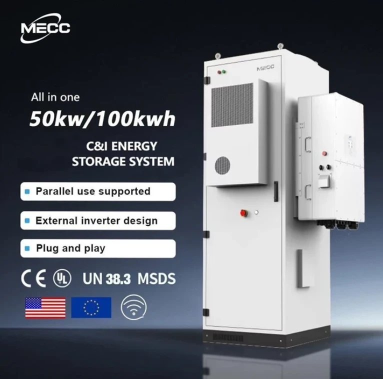
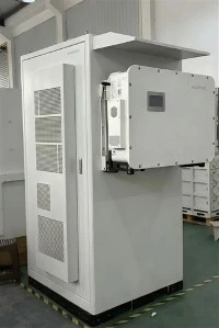
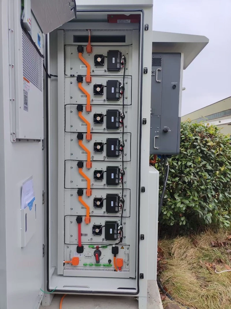
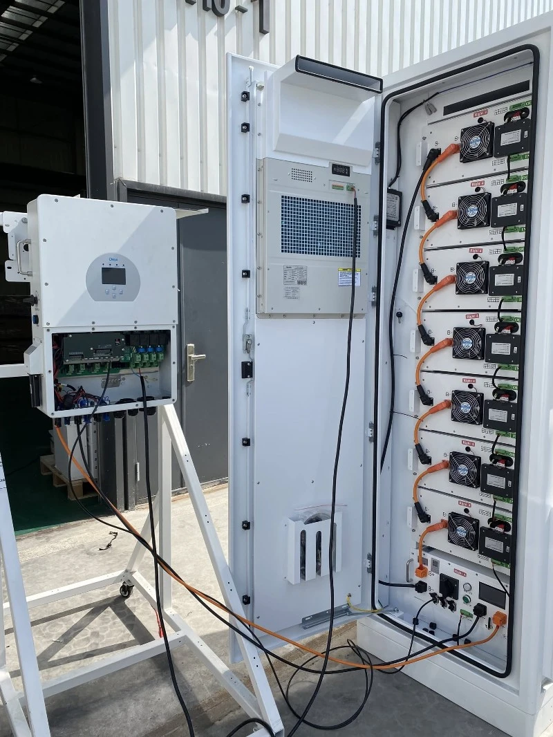
MECC 50KW 112KWH BESS Battery Energy Storage System
The MECC 50kw 112kWh Battery Energy Storage Cabinet is a high-capacity energy storage solution designed for industrial and commercial applications. Featuring 358V, 314Ah lithium iron phosphate (LiFePO4) battery, it ensures long-lasting, safe, and efficient energy storage.
High-efficiency 50kW/112kWh Industrial and Commercial Energy Storage System (C&I ESS). Features LiFePO4 battery, peak shaving, and smart EMS. Reduce operational costs and ensure power backup. Inquire for custom BESS solutions.
Designed with a compact footprint of less than 1.2 square meters, this 112kWh cabinet features a pre-integrated all-in-one design, reducing on-site installation time by 40% compared to modular rack systems.