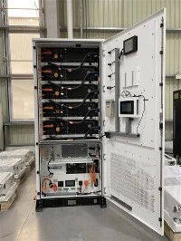
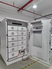
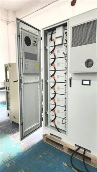
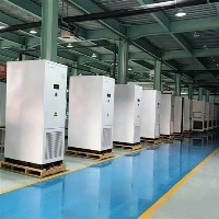
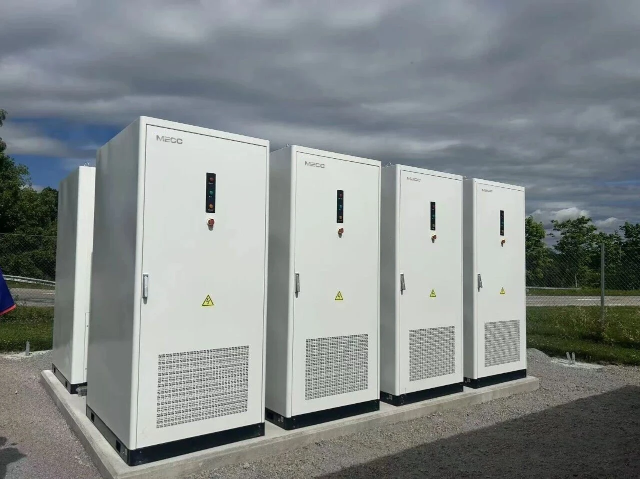
This project is located in an automotive‑component industrial park across Eastern Europe. The end‑user is a precision machining factory equipped with an 800 kW rooftop PV system. Limited transformer capacity, substantial peak‑valley electricity price gaps, and zero tolerance for unplanned shutdowns define the site requirements. The system is rated at 4 MW / 8.24 MWh, built upon 8 × 500 kW PCS units connected in parallel on the 480V AC bus, paired with 8 clusters of 261 kWh liquid‑cooled lithium‑iron phosphate batteries. Key functional demands cover peak‑valley arbitrage, maximum demand control, PV fluctuation mitigation, and reliable islanded microgrid operation for critical manufacturing loads.
Initially, the customer adopted a third‑party solution relying only on native PCS local parallel functions without upper‑level cluster controllers. During preliminary commissioning, the system suffered typical multi‑parallel malfunctions and could not run stably at full power. MECC replaced the control architecture with a full cluster‑coordinated solution to complete rectification and final delivery.
Four Typical Multi‑parallel Faults and Root‑cause Analysis
Fault 1: Power‑frequency circulating current, frequent PCS over‑current alarms and cross‑cluster battery charging‑discharging
On‑site symptoms: During grid‑tied loading tests, abnormal deviations appeared in PCS power sampling. Distorted output current and excessive cabinet surface temperature were observed. Over‑current protections frequently tripped random PCS units offline. BMS background logs revealed bidirectional cross‑cluster current: some battery clusters charged while others discharged simultaneously, driving expanding voltage discrepancies between clusters.
1.Hardware zero‑point drift and temperature‑driven sampling offset created minor output‑voltage differences among PCS modules. Given the extremely low impedance of the low‑voltage busbar, even small voltage gaps generated severe power‑frequency circulating current.
2.Without unified synchronisation clock signals, every PCS ran its independent phase‑locked loop (PLL). Tiny phase‑angle deviations induced active and reactive circulating current.
3.Mismatched internal filter inductors and on‑site cable loop impedances aggravated steady‑state circulating current.
4.Unsynchronised closing timings for paralleling breakers produced inrush circulating current at grid‑connection moments.
Circulating current overheated power semiconductors and shortened module service life. Cross‑cluster circulating current caused invalid charge‑discharge cycles and accelerated battery capacity decay, eroding project revenue.
Fault 2: Severe uneven load sharing: some PCS ran at full load while others operated under‑loaded or idle
On‑site symptoms: When a 2.4 MW total discharge command was issued, output diverged sharply across 8 PCS units. Two units approached 500 kW full rating, three delivered less than 80 kW, and the rest stayed nearly idle. Sustained high temperatures forced derating on heavily loaded units, lowering the system's usable capacity and creating imbalanced equipment wear.
Root cause: No upper controller assigned power set‑points. Each PCS responded autonomously to bus‑bar load signals. Differences in inner‑loop response speed and control bandwidth allowed faster‑responding units to capture most of the load while suppressing output from slower devices.
Fault 3: Resonance triggered by paralleled LCL filters, waveform distortion and cascading disconnection
On‑site symptoms: During rooftop PV switching or large motor start‑stop events, bus‑bar voltage distorted, harmonic content amplified, and voltage flicker occurred. Oscillating output currents repeatedly activated over‑voltage and over‑current protection, causing cascading PCS trips and complete energy‑storage shutdown.
Root cause: Each PCS integrates built‑in LCL output filters. When eight units paralleled, cumulative inductance‑capacitance parameters resonated with transformer leakage inductance and line impedance of the plant network. Operating‑condition disturbances excited resonance, degrading overall power quality.
Fault 4: Failed island‑mode transition under grid loss, voltage collapse and loss of critical loads
On‑site symptoms: In simulated blackout tests, partial PCS switched to VF voltage‑source mode while others remained in grid‑tied PQ current‑source mode. Severe instantaneous power shocks crashed bus‑bar voltage. Island establishment failed, and essential processing equipment lost power consistently.
Root cause: No centralised island‑detection logic. Each PCS judged grid status independently, resulting in inconsistent mode‑switch timings. Once entering island VF operation, multiple PCS generated independent voltage references, giving rise to violent circulating current and voltage oscillation inside the microgrid.
MECC Targeted Comprehensive Solution
The solution centres on an energy‑storage cluster controller to realise three‑layer coordination among EMS, BMS and PCS. Existing 500 kW PCS and battery clusters were retained. A central cluster master unit was deployed together with optimised PCS firmware and improved on‑site construction standards to resolve the four parallel‑operation risks systematically.
1. Circulating‑current suppression via centralised master‑control synchronisation
1.The cluster controller broadcasts unified synchronisation clock, voltage amplitude and phase reference signals. Slave PCS units disable local independent PLL and follow PLL references delivered by the master controller, running only inner‑loop current tracking. This eliminates circulating current triggered by phase and frequency inconsistencies at source.
2.The cluster controller synchronises breaker‑closing commands to eliminate inrush circulating current during paralleling.
3.Real‑time data exchange between BMS and cluster controller mitigates DC‑side cross‑cluster circulating current driven by battery‑voltage divergence.
4.Field installation standardised cable length and cross‑section for parallel loops to minimise impedance mismatch.
After rectification, steady‑state circulating current dropped below 1 % of rated current. Over‑current tripping caused by circulation disappeared, and bidirectional cross‑cluster battery current was largely eliminated.
2. Balanced load distribution: centralised power set‑point allocation with weighted loading
1.The upper‑layer EMS‑cluster controller receives overall charge‑discharge power targets and distributes active and reactive power proportionally according to PCS rated capacity. For a total 2.4 MW output across eight PCS, each receives an accurate 300 kW assignment, removing local "load‑grabbing" behaviour.
2.Dynamic weighted‑loading algorithms are supported. Based on SOC and temperature fed back by BMS, PCS connected to cooler batteries with favourable SOC take proportionally more load. Units attached to hot or boundary‑SOC clusters derate moderately to equalise stress across hardware.
3.Upon single‑unit faults, the cluster controller instantly redistributes power and smoothly transfers load to healthy PCS to preserve overall output capacity.
After commissioning, output deviation among PCS stays within ±3 % under arbitrary total‑power commands, ending the full‑load / idle imbalance.
3. Resonance suppression: software‑based active damping for LCL filters
Instead of adding lossy hardware damping resistors, all PCS received firmware upgrades to activate active‑damping control. The algorithm implements differential feedback of LCL filter capacitor current, virtually increasing system damping in software and suppressing resonance peaks generated by multi‑unit paralleling.
Additionally, the EMS enforces power‑ramp rate limits to smooth transients from PV volatility and abrupt load changes. Repeated disturbance tests with PV and impulse loads show THD maintained below 3 %. Resonance‑induced cascading trips no longer occur.
4. Consistent island‑transition control with millisecond‑level synchronous switching and master‑source redundancy
1.The cluster controller acts as the sole island‑judgement hub. Once grid failure is detected, millisecond‑level synchronous commands trigger all PCS to switch simultaneously from grid‑tied PQ current‑source mode to island‑operated VF voltage‑source mode, avoiding timing chaos of partial switching.
2.Under island conditions, one PCS serves as the master VF reference source delivering 480 V / 50 Hz; all remaining units operate as current‑following slaves without generating independent voltage references, preventing oscillation and circulation from multiple paralleled voltage sources.
3.Redundant master‑node election is implemented. If the island master reference PCS fails, the cluster controller rapidly selects another healthy unit to take over voltage regulation, avoiding full‑microgrid collapse from single‑point failure.
4.Protection interlocks ensure that when any PCS trips during island operation, remaining units rapidly compensate for power gaps and sustain power supply for critical plant loads.
Multiple blackout‑simulation and grid‑recovery tests verified seamless island transitions without voltage collapse. Essential production loads maintained uninterrupted power supply.
Project Operational Outcomes
Following commissioning and rectification, the system has run stably for more than eight consecutive months.
1.The four core multi‑parallel risks - circulating current, uneven load sharing, resonance oscillation, and defective island switching - have been fully resolved. The 4 MW full charge‑discharge capability of eight paralleled PCS is reliably achieved.
2.Peak‑valley arbitrage, PV smoothing and demand management function as designed and effectively cut monthly energy expenditure for the factory. Island‑mode performance passes all simulation tests and satisfies industrial non‑stop‑operation requirements.
3.Temperature and SOC balance across PCS and battery clusters are greatly improved. Abnormal ageing risks are reduced and the whole‑system lifecycle is extended.
This project demonstrates that multi‑PCS parallel C&I energy‑storage cannot rely merely on built‑in local parallel functions. Cluster‑level EMS‑BMS‑PCS coordinated master control constitutes the core prerequisite for stable large‑scale parallel‑system operation. It is also critical for overseas C&I projects to avoid commissioning failures and secure long‑term economic returns.
Large‑capacity overseas C&I energy‑storage frequently adopts AC‑side multi‑PCS parallel topologies. Circulating current, imbalanced load distribution, LCL‑filter resonance, and asynchronous island‑mode switching are highly prevalent engineering challenges. In many field cases, root causes are not component hardware defects but missing upper‑layer cluster coordination. Standalone local PCS parallel logic cannot cope with complex industrial‑site conditions.
MECC's centralised cluster‑master‑control solution systematically addresses multi‑parallel pain points via unified clock synchronisation, centralised power allocation, software‑based active‑damping resonance mitigation, globally synchronised island detection, and master‑slave redundant architecture. Validated on multiple European 2‑6 MW C&I energy‑storage sites, it delivers replicable engineering practices for comparable global multi‑parallel C&I ESS deployments.
Liquid Cooling 125KW 261kWh Lithium Battery Energy Storage Cabinet
The IP55 Protected All-in-One Solar Energy Storage Cabinet is a high-performance, integrated energy solution engineered for outdoor commercial, industrial, and utility-scale solar applications. It integrates a 125kW Power Conversion System (PCS), a 261kWh lithium iron phosphate (LiFePO4) battery bank, an advanced liquid cooling system, and a intelligent Battery Management System (BMS) into a single cabinet with IP55 weatherproof protection. Designed to withstand harsh outdoor environments while delivering efficient energy conversion and storage, it supports solar energy absorption, peak shaving, load shifting, grid auxiliary services, and emergency backup power. Ideal for utility-scale solar farms, industrial parks, large commercial complexes, and remote microgrids, it provides a reliable, space-saving, and low-maintenance solution for large-scale renewable energy integration.