


Abstract
When it comes to the ability of battery management system integrated circuits (BMS ICs) to resist electromagnetic interference (EMI), we need to talk about the layout of printed circuit board (PCB) wiring and external components (ECs), which are key roles. Don't forget, the impedance of BMS IC itself is also a big deal. In fact, this impedance will undergo significant changes due to the battery balancing function of BMS IC. Specifically, most BMS ICs on the market integrate passive battery balancing function, which greatly reduces the impedance presented by BMS ICs. The purpose of our study is to understand the impact of different passive battery balancing methods on the immune level of BMS ICs. Then, we also proposed a new BMS IC architecture that not only reduces the number of external components, but also maximizes the impact of passive battery balancing on the IC's immunity, that is, the injection level in direct power injection (DPI) testing. In this way, even in noisy environments, the IC can maintain high-precision high voltage measurements.
1. Introduction
Lithium ion (Li Ion) batteries and battery management systems (BMS) have been widely studied, aiming to pave the way for the new generation of electric vehicles (EV) and hybrid electric vehicles (HEV). For example, a major aspect of development is to characterize the conducted electromagnetic interference (EMI) from the drive inverter, which is one of the noise sources that may cause interference to the BMS IC. In this noise path, cables, PCB routing, and external components (ECs) have a significant impact on the immunity of BMS IC. The ECs being focused on here are high-voltage rated capacitors for automobiles used to prevent electrostatic discharge (ESD). As shown in previous work, the cheapest configuration for these ECs is differential connections across batteries. However, this will result in an increase in injection level due to the introduction of resonance within the direct power injection (DPI) frequency range ([150kHz; 1GHz]), which is caused by the constructed C-L ladder network.
In this case, passive battery balancing will connect the battery balancing resistor and some parasitic components in parallel with the ESD capacitor when activated, which may change the attenuation level of these resonances. This study considers two battery balancing methods. The first method is to exclude the battery currently being measured by the BMS IC, short-circuit all batteries that can be shorted, and then extract the injection level of the measured battery during DPI to evaluate the impact of this method on the IC's immunity. In addition, this study compared two architectures using this first balancing method, with the main difference being the number of batteries that can be balanced simultaneously. The second balancing method is to short-circuit the same battery currently measured by the IC in a specially proposed architecture. In addition, due to the new placement of balancing resistors, the proposed architecture turns the ESD capacitor into a filter, which enables balancing to significantly reduce the impedance seen on the BMS side, thereby lowering the injection level. In addition, to evaluate the effect of parasitic inductance, the impact of battery balancing at different distances between ESD capacitors and ICs was also assessed.
Finally, the structure of this article is as follows: Firstly, the modeling of BMS IC environment is introduced; Secondly, using the first battery balancing method, compare the impact of balancing on injection level between two BMS IC architectures during DPI; Thirdly, introduce the proposed architecture and evaluate its impact on injection level balance during DPI using the second balancing method.
2. BMS integrated circuit environment modeling
BMS function and DPI testing: The main purpose of BMS is to ensure the optimal and safe operation of batteries in harsh electromagnetic interference (EMI) environments. Some of the main functions of BMS IC include precise measurement of battery voltage and passive battery balancing to prevent battery degradation and achieve optimal power extraction from the battery pack. To characterize the ability of ICs to perform these tasks in harsh EMI environments, direct power injection (DPI) testing was conducted by coupling 30dBm power in common mode (CM) to all IC inputs connected to the battery.
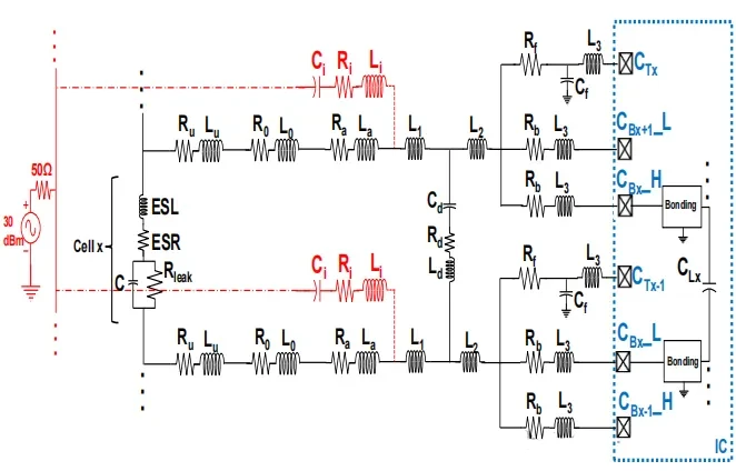
DPI test setup and related components: Figure 1 shows the DPI setup used in this study, using a BMS IC product that can monitor up to 18 batteries. This setting introduces supercapacitors to construct battery packs with voltages higher than 80V using 12V batteries and stabilize the impedance on the battery pack side. From Figure 1, it can be seen that the current modeling methods focus on elements such as the battery pack and 30cm cables on each side of the PCB, supercapacitors, connectors, PCB wiring on the supercapacitor board and BMS IC board, external components (ECs) on the BMS IC board, and the impedance presented by the BMS itself.

BMS IC environment modeling: From Figure 2, the BMS IC input is modeled by capacitor C {L} (30pF) representing the internal passive battery balancing switch, with switch on resistance Ron=0.25 Ω. The capacitor C {d} (47nF) used for ESD purposes is the ECs of concern, which adopts the cheapest configuration. The model also includes the parasitic resistance and inductance of C {d} (parasitic resistance R {d} takes values at frequencies of 100MHz and above), while considering the parasitic behavior of injected capacitor C {i} (330pF). Due to the presence of relatively high values of capacitance C {d}, the capacitance effect of cable and PCB routing has not been considered. The battery is modeled using an ideal voltage source because the battery pack and cables are short circuited by supercapacitors. All parameters of the 18 batteries in Figure 2 are similar, ignoring the mismatch in the distance between each battery and the IC pin. This model is effective in the range of [150kHz, 200MHz].


IC pin and architecture related situation: In Architecture 1, there is a C {Bx} pin used for battery voltage measurement and passive battery balancing, as well as a C {Tx} pin used only for battery redundancy voltage measurement. The measurement through the C {Tx} pin is performed by a discrete-time analog-to-digital converter (DT ADC), therefore an anti aliasing filter (AAF, i.e. R {f} and C {f}) is required; The measurement through the C {Bx} pin is performed by a continuous time analog-to-digital converter (CT ADC) without the need for AAF. The next section will introduce Architecture 2 and the first balancing method used in this study to improve the immunity of BMS IC. It will also compare the injection level attenuation brought by the first passive battery balancing method between Architecture 1 and Architecture 2. In addition, this study assumes that the battery equilibrium activation lasts for several hundred microseconds, which is sufficient for voltage measurement of the interested battery, and therefore will not have a significant impact on the state of charge of the equilibrium battery.
3. Differences in BMS IC architecture, resonance issues, and the impact of the first balancing method
Architectural differences and resonance phenomena: The pin arrangement of BMS ICs, the number and type of analog-to-digital converters (ADCs) used, and other architectural aspects directly affect external components. In Architecture 1 (Figure 2), except for C_{B0} and C_{B19}, each C_{Bx} pin is shared by two batteries. Due to the need to set R_ {b} on each PCB trace leading to the C_{Bx} pin in DPI testing to limit the conversion from common mode (CM) to differential mode (DM), adjacent batteries cannot be balanced simultaneously, and odd and even batteries need to be balanced at different periods. Architecture 2 (Figure 3) has an additional C {Bx \ _ H} pin that can balance adjacent batteries simultaneously, but it will increase the chip size, pin count, and external components (R {b}). The C-L trapezoidal network composed of L_ {T} (L_ {u}+L_ {0}+L_ {a}) and C_d} will generate multiple resonances, which have relatively low frequencies (below 10MHz). In practical applications, the cable connecting BMS IC and battery pack can reach 2 meters, which will lower the resonance frequency and higher the quality factor. Although R_ {T} (R_ {u}+R_ {0}+R_ {a}) can attenuate the resonance to a certain extent, the effect is insufficient.

The first balancing method and its impact on injection level: The first balancing method considered in this study is to extract the peak to peak voltage of the first battery (C_{L1}) in DPI simulation while balancing other batteries. For architecture 1, only odd numbered batteries (excluding battery 1) are balanced, as balancing even numbered batteries (starting from battery 2) would alter the direct current (DC) of battery 1, which is not in line with actual measurement scenarios. For architecture 2, all batteries except for battery 1 can be balanced. Evaluate by conducting transient simulations in the spice environment (providing sufficient period stability to the signal, extracting specific period average peak to peak voltage, and taking sufficient points in the range of [150kHz; 200MHz]). The results showed that passive battery equalization reduced the resonance amplitude as expected at low frequencies, but increased the injection level at high frequencies (approximately 150MHz). Architecture 2 has a greater impact on injection level due to battery balancing at low frequencies, as it can balance more batteries simultaneously and introduce more damping; At high frequencies, its inherent injection level is lower than that of architecture 1, and after activating the battery balance, there is only a slight improvement in high frequencies. In addition, there is a trade-off between the value of the battery balancing resistor $R_ {b} $and the injection level. Reducing R_ {b} will enhance low-frequency resonance attenuation but weaken high-frequency resonance attenuation, while increasing R_ {b} will have the opposite effect.


4. Analysis of the Second Equilibrium Method and Proposal of a New Architecture
Analyze ideal scenarios and improvement strategies: To evaluate the impact of battery balancing on low-frequency resonance, analyze an ideal and simplified scenario (similar to architecture 1 but simplified). At frequencies below 5MHz, supercapacitors can be considered as short circuits due to their high capacitance value (10F) and parasitic parameters (equivalent series resistance ESR, equivalent series inductance ESL) being low in this range; When considering low-frequency resonance, C {L} can be ignored; Adopting a simple trapezoidal network without external load is convenient for analysis. For the total impedance in this scenario (Formula 1), the resonance frequency was calculated using a specific expression (Formula 2). It was found that under the given parameters, the discriminant of Formula 2 is negative, with two imaginary roots, and the real part reflects resonance attenuation (pseudo periodic state, Formula 3). For the simplified implementation scenario of battery balancing in Figure 7b, the polynomial of resonance was calculated (Formula 4). It was found that reducing the resistance R as much as possible can make more discriminative expressions of resonance index positive, significantly attenuating the resonance frequency, but some resonances are still in a pseudo periodic state. The attenuation factor (Formula 5) indicates that if R is low enough, battery balancing can significantly affect the injection level. Although increasing the resistance can improve R_ {T}, it is not feasible for architectures 1 and 2 because it will reduce the measurement accuracy of the C_ {Tx} pin during battery balancing.


Propose a new architecture and performance evaluation: Propose a new architecture in which the measurement of the C {Tx} pin uses a continuous time analog-to-digital converter (CT ADC) without the need for anti aliasing filters (AAF, i.e. R {f} and C {f}), the measurement of the C {Bx} pin uses a discrete time analog-to-digital converter (DT ADC), and the balance resistor R {b} is moved before the ESD capacitor C {d}, saving components and enhancing low-frequency resonance attenuation. To prevent measurement errors during battery balancing, the measurement of C {Tx} is performed before R {b}. The second balancing method balances the battery being measured (such as cell x, Figure 8) to reduce the injection level of the C {Tx} pin. The new architecture maximizes the impact of battery balancing on DPI injection level by placing R {b} before C {d} and bringing C {d} closer to the IC. The simulation results show that the new architecture has a lower inherent injection level than the old architecture when battery balancing is not activated (Figure 5), and significant attenuation can be obtained when C {d} is placed at a reasonable distance from the IC (0.5cm or 1cm) (Figure 9). However, there is a trade-off in ESD performance in the new architecture. In architectures 1 and 2, when an ESD event occurs, C {d} provides a low impedance ground path for the pin, while in the new architecture, R {b} poses a high voltage risk to the C {Tx} pin. Therefore, R {b} needs to choose an appropriate value or place an internal clamping device on C {Tx} to alleviate the issue. Future work will focus on improving the ESD performance of the new architecture.


5. Summary
This study proposes a battery management system integrated circuit (BMS IC) model for practical direct power injection (DPI) simulation, proposes the first battery balancing method to reduce the injection level during DPI, and compares the performance of two architectures under this method. By establishing a simple analysis model, exploring the impact of battery balancing on the attenuation level of low-frequency resonance, and determining strategies to reduce the coupling of low-frequency important noise. Propose a new architecture that reduces the number of external components and injection levels, making battery balancing more important for IC immunity.
The new architecture has trade-offs related to electrostatic discharge (ESD) performance. Future work will focus on evaluating the ESD performance of the new architecture and exploring possible improvement measures without excessively increasing the number of external components, in order to optimize the overall performance of the new architecture, better apply it to practical battery management systems, improve the system's performance in electromagnetic compatibility, ensure the stable operation of the battery management system in complex electromagnetic environments, and balance cost and performance.