Lithium‑Ion Battery Thermal Runaway Mechanism

Aug 14, 2026 Leave a message

Once thermal runaway (TR) is triggered, lithium‑ion batteries can rapidly develop into fire, explosion and even complete vehicle burnout under appropriate conditions. How does a minor internal defect or external abuse‑induced damage evolve step‑by‑step into an uncontrolled high‑temperature chain reaction? This article summarizes the whole process of lithium‑ion battery thermal runaway from three perspectives: triggering incentives, internal chemical reaction processes and external thermal‑runaway evolution stages, together with key temperature thresholds and dominant reaction mechanisms.


1. Abuse Conditions for Thermal Runaway


Generally, thermal runaway of lithium‑ion batteries is induced by three types of abuse: mechanical abuse, electrical abuse and thermal abuse.
 
Mechanical abuse is usually caused by external forces such as collision, crushing or penetration, which may damage internal battery structures and further trigger thermal runaway. Electrical abuse covers overcharge, overdischarge, external short circuit and internal short circuit, which directly break the chemical equilibrium inside batteries. Thermal abuse refers to battery operation under high‑temperature ambient conditions or local overheating, which directly triggers material decomposition and chain reactions.
 
 
1.1 Mechanical Abuse
 
Mechanical abuse can be further divided into collision‑crush and penetration scenarios.
 
 
Collision and Crush
 
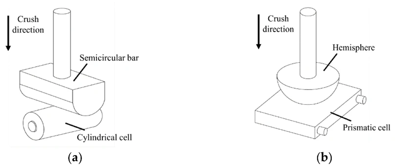
When a battery suffers external crushing or collision, the separator may tear, bringing the positive and negative electrodes into direct contact and forming an internal short circuit. The internal short circuit generates excessive local current and massive heat, which further induces thermal runaway.
 

1

 
Penetration
 
When a sharp object pierces the battery, the separator is directly damaged and an internal short circuit occurs. Electrolyte leakage may take place during penetration, further raising thermal‑runaway risks.
 
Thermal runaway triggered by mechanical abuse is normally accompanied by severe physical deformation and electrolyte leakage, and internal short circuits may release tremendous energy instantaneously.
 

2


1.2 Electrical Abuse
 
Electrical abuse includes internal short circuit, external short circuit, overcharge and overdischarge. Among them, internal short circuit and overcharge are the two dominant forms.
 
 
Overcharge
 
When charging voltage exceeds the upper limit, lithium ions continuously deintercalate from the cathode, destabilizing cathode materials such as NCM and LCO. Structural collapse may occur with oxygen release. The released oxygen reacts with electrolyte and generates substantial heat. Meanwhile, graphite anodes become lithium‑saturated. Once the anode can no longer accommodate additional lithium, lithium dendrites precipitate on the anode surface and pierce the separator to induce internal short circuits. Existing research indicates that electrolyte oxidation and reactions between lithium dendrites and electrolyte contribute most to heat generation during overcharge.


3

 
Overdischarge
 
When discharge voltage drops excessively, copper current collectors on the anode dissolve and migrate toward the cathode, forming copper dendrites that pierce the separator and cause internal short circuits. In addition, overdischarge damages the SEI film, enabling direct exothermic reactions between electrolyte and the anode. The figure illustrates copper dissolution and internal‑short‑circuit formation triggered by overdischarge. Internal short circuits induced by copper deposition occur when the battery is overdischarged below ‑12 % SOC and get aggravated with further overdischarge.


4


Internal Short Circuit
 
Internal short circuits are mostly caused by separator damage under various conditions, which creates direct contact between positive and negative electrodes and releases large amounts of heat. This process may fracture adjacent separators and propagate thermal runaway inside the cell. Subsequent separator shrinkage brings about large‑scale internal short circuits and eventually triggers thermal runaway.
 

51


52


External Short Circuit


When positive and negative terminals are directly connected via external conductors, high current flows through the battery and produces Joule heat, leading to rapid temperature rise and thermal runaway.


1.3 Thermal Abuse


Both mechanical and electrical abuse may induce internal short circuits and generate heat. If such heat cannot be dissipated efficiently, temperature keeps climbing and may eventually cause catastrophic battery failure. Specific stages and temperature thresholds vary across different battery chemistries, yet the overall evolution path generally follows the thermal‑runaway progression illustrated in relevant diagrams.


61


The three abuse modes are not independent but interlocked in a chain sequence. Mechanical abuse often acts as the starting point: it gives rise to electrical abuse, which then evolves into thermal abuse and finally thermal runaway. Mechanical abuse leads to electrical abuse because external force ruptures internal separators and enables cathode‑anode contact, i.e., internal short circuit as one form of electrical abuse. Electrical abuse turns into thermal abuse because internal short circuits release massive heat and activate high‑temperature chemical reactions that produce even more heat, equivalent to continuous external heating. Thermal runaway occurs once heat accumulates beyond critical thresholds.


62


When battery temperature rises above approximately 70 °C, the solid‑electrolyte interphase (SEI) film begins to decompose, exposing fresh graphite surfaces to electrolyte. SEI‑film reconstruction is exothermic and pushes temperature higher. If temperature further exceeds roughly 130 °C, polymer separators made of polyethylene or polypropylene melt, causing direct contact between anode and cathode and internal short circuits. Short‑circuit heat release severity strongly depends on battery state‑of‑charge (SOC). When temperature goes above 200 °C, electrolyte and cathode materials undergo thermal decomposition, releasing highly flammable oxygen as well as toxic hazardous substances such as hydrofluoric acid, further elevating safety hazards.
 

64


65


2. Internal Reaction Mechanisms during Thermal Runaway


Thermal runaway represents superposition of sequential exothermic side reactions. As temperature increases step‑wise, individual reactions are activated at their respective threshold temperatures. These reactions release large quantities of heat and accelerate subsequent violent reactions, forming a self‑accelerating feedback loop. The sequence normally starts with SEI‑film decomposition, followed by electrolyte decomposition, separator melting, cathode‑material decomposition and oxygen release. These reactions couple and reinforce one another.
 
 
1.Electrolyte‑salt decomposition
 
Electrolytes consist of lithium salts and organic solvents. Typical lithium salt is lithium hexafluorophosphate (LiPF₆); common organic solvents include ethylene carbonate (EC), dimethyl carbonate (DMC), propylene carbonate (PC), etc.
LiPF₆ is thermally unstable and decomposes at relatively low temperatures of 60‑70 °C with moderate heat output. Its decomposition product PF₅ promotes subsequent reactions.


2.SEI‑film decomposition


The SEI features electronic insulation and ionic conductivity. It protects the anode and prevents direct anode‑electrolyte contact. SEI breaks down at 80‑130 °C, converting unstable SEI components into stable ones.

This process is exothermic; heat generation correlates positively with anode surface area. Studies confirm heat released from SEI decomposition serves as one origin of thermal runaway.
 
 
3.Anode‑electrolyte reactions
 
Once SEI ruptures, the anode is directly exposed to electrolyte and undergoes exothermic reactions that generate large volumes of flammable gas, aggravating internal temperature rise and pressure build‑up.
Reactions are anode‑dominant under low‑electrolyte conditions, whereas electrolyte‑dominant reactions prevail with abundant electrolyte.
 
 
4.Cathode decomposition and oxygen release
 

Cathodes decompose and undergo oxidation reactions at 170‑300 °C with oxygen release. This stage delivers the fastest heat‑generation rate and poses the highest hazards during thermal runaway. Decomposition temperatures and behaviors differ significantly among cathode chemistries.


For layered NCM (nickel‑cobalt‑manganese) or NCA (nickel‑cobalt‑aluminum) cathodes, crystal‑structure collapse and O₂ release take place at 170‑250 °C.
 
 
Released oxygen supplies oxidants for electrolyte combustion, transforming the battery interior from an oxygen‑deficient environment into an enclosed combustion source that sustains combustion even inside sealed spaces. In contrast, olivine‑structured LFP (lithium‑iron‑phosphate) cathodes exhibit superior structural stability. Their decomposition temperature is around 300 °C with no oxygen evolution, leading to relatively mild thermal‑runaway behavior. Nevertheless, oxygen from ambient air entering through ruptured safety valves or damaged housings can still accelerate reactions.
 
 
5.Massive electrolyte decomposition coupled with internal short circuit
 
Released oxygen reacts vigorously with EC and DEC solvents, generating tremendous heat and carbon dioxide.
DEC also reacts with PF₅ originating from LiPF₆ decomposition mentioned above.
Cathode thermal decomposition and cathode‑electrolyte reactions accumulate massive heat within short durations, constituting the root cause of thermal‑runaway initiation.
 
 
6.PVDF binder decomposition
 
PVDF binder is indispensable for battery manufacturing. It decomposes above 230 °C and releases substantial heat. Research demonstrates this reaction further exacerbates thermal‑runaway severity.


3. Division of Thermal‑Runaway Stages
 
 
Existing research defines three characteristic temperatures for thermal runaway: onset self‑heating temperature (T₁), thermal‑runaway trigger temperature (T₂), and peak thermal‑runaway temperature (T₃).
 

7


1.Onset self‑heating temperature (T₁)
 
T₁ is defined as the point where temperature‑rise rate reaches 0.02 °C/min. Between T₁ and T₂, abnormal heat generation emerges while thermal‑runaway critical conditions are not yet satisfied. This temperature window normally ranges from 50 °C to 140 °C. In this phase, SEI starts decomposing and metal ions dissolve. Internal chemical reactions intensify progressively without large‑scale thermal‑runaway events.
 
 
2.Thermal‑runaway trigger temperature (T₂)
 
T₂ corresponds to a temperature‑rise rate of 1 °C/s. Upon reaching T₂, the battery enters formal thermal‑runaway status. Separators dissolve massively, cathode‑anode isolation fails, and internal chemical reactions accelerate sharply. The T₂‑to‑T₃ temperature range typically spans 140 °C to 850 °C. Heat‑generation rate outpaces heat‑dissipation capacity and temperature keeps surging. Severe physical‑chemical changes occur: separator rupture, lithium‑electrolyte reactions, chemical crosstalk and separator burnout. Once temperature passes T₂, cathode‑anode direct contact occurs and thermal‑runaway reactions become irreversible.
 
 
3.Peak thermal‑runaway temperature (T₃)
 
T₃ represents the maximum temperature achieved throughout thermal runaway. After hitting T₃, the thermal‑runaway termination phase begins. Battery structures suffer severe damage, chemical and physical activities stabilize until energy is fully released. T₃ can be used to evaluate potential module‑level thermal propagation risks.


Summary
 
 
With official implementation of GB 38031‑2025, thermal‑safety requirements for electric‑vehicle traction batteries have been further upgraded. The new standard renders "no fire, no explosion" for traction batteries a mandatory requirement. It specifies 7 test items for battery cells and 17 items for battery packs, and adds thermal‑propagation testing: systems must trigger alarms 5 minutes in advance without fire or explosion. These updates indicate that thermal runaway is not an occasional accident but a core risk requiring systematic management.
 
Understanding how mechanical, electrical and thermal abuses couple and propagate, as well as the evolution of electrical, thermal, mechanical and gas‑phase signals during thermal‑runaway processes, lays the foundation for advancing battery thermal‑safety design.


Send Inquiry

whatsapp

Phone

E-mail

Inquiry