


For solar installers, EPC contractors, and energy storage system technicians, learning how to wire a split phase inverter correctly is essential for safe, code-compliant, and stable system operation. Improper split phase inverter wiring is one of the top causes of phase imbalance, frequent system tripping, inspection failure, and premature inverter damage in US residential and commercial 120/240V energy storage projects. This step-by-step guide covers NEC-standard procedures, key terminal rules, wire sizing, and common mistakes to deliver reliable 120/240V split phase inverter installation for all American standard grid systems.
Basic Split Phase Inverter Wiring Principles
Unlike single-phase inverters, American standard split phase inverters are designed for the unique North American dual-leg grid structure, consisting of L1 hot wire, L2 hot wire, neutral wire, and ground wire. The core purpose of professional split phase inverter L1 L2 neutral wiring is to maintain balanced voltage output between the two phases, supporting both 120V single-phase loads and 240V high-power equipment. Standard split phase inverters rely on symmetric dual-leg conduction; unbalanced or misconnected terminals will directly trigger internal protection mechanisms and disrupt normal power output.
Pre-Wiring Preparation & Wire Sizing Standards
Before starting installation, complete full power cutoff and use a multimeter to verify circuit safety, complying with US electrical safety regulations. Reasonable wire gauge selection is critical to avoid overheating and power loss. Following NEC compliant split phase inverter wiring rules, low-power split phase inverters apply 10AWG to 12AWG wires, while medium and high-power models require 6AWG to 8AWG thickened cables based on output current and wiring distance. Additionally, reliable system grounding is mandatory for outdoor ESS units to prevent leakage current and static damage.
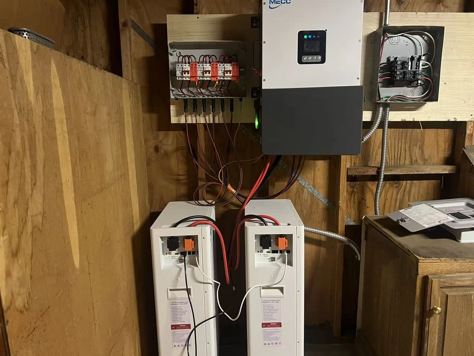
Step-by-Step Guide to Correct Split Phase Inverter Wiring
Professional installation follows a fixed DC-first, AC-second workflow. First, complete DC battery wiring, strictly confirming positive and negative polarity to avoid reverse connection damage and ensuring tight terminal crimping. Second, connect the neutral wire and ground wire firmly; stable neutral connection is the foundation of balanced 120V phase voltage output.
Third, install L1 and L2 dual hot legs with symmetric wiring, avoiding phase sequence reversal and inconsistent wire length. Fourth, distinguish grid input and load output terminals for targeted connection to prevent reverse circuit transmission. Finally, power on the system to conduct phase balance testing, verifying that the voltage difference between L1 and L2 is within the standard range and no unbalance alarms appear.
Special Scenario: Single 120V Phase Wiring Setup
For old residential sites with only 120V single phase power, split phase inverters support adaptive single-leg operation. Installers only need to connect a single hot leg with neutral and ground wires, then switch the inverter to single-phase operation mode in system settings. Note that this setup causes power derating and cannot support 240V loads, which is a key limitation for low-voltage grid renovation projects.
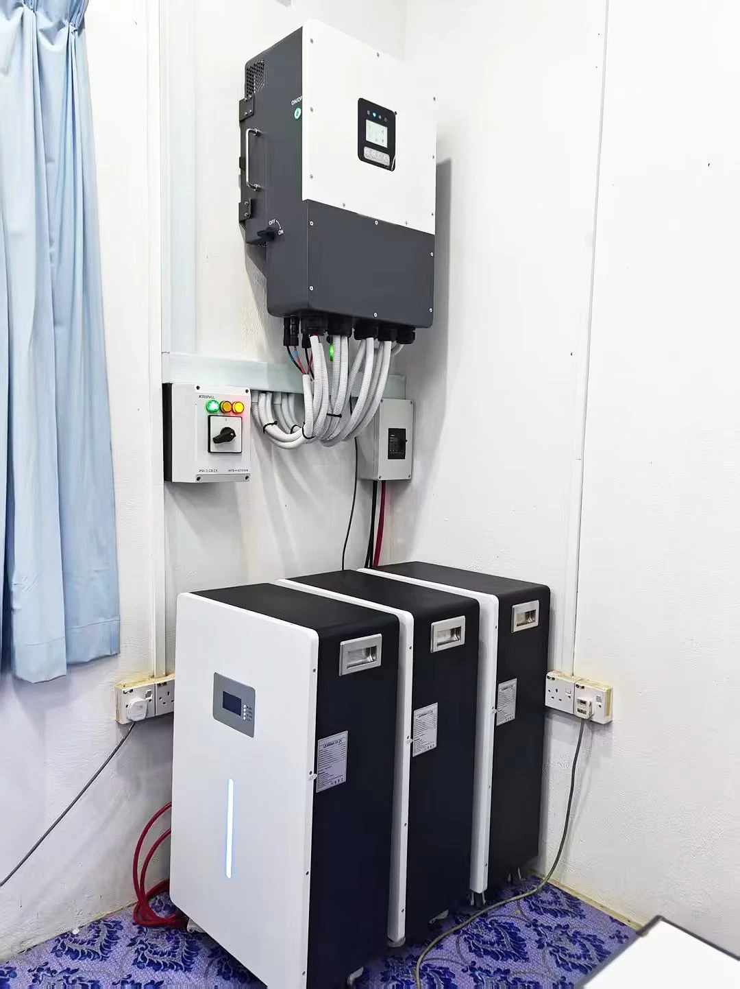
Common Wiring Mistakes to Avoid
Most on-site faults stem from typical operational errors. Reversed L1 and L2 wiring leads to phase detection failure and unstable output. Loose neutral connections cause severe voltage fluctuation, while missing grounding triggers safety hazards. Using mismatched wire sizes results in line overheating and power attenuation, and uneven load distribution frequently activates overbalance protection. Mastering US split phase inverter wiring best practices effectively eliminates these avoidable failures.
FAQ
1. What happens if L1 and L2 are reversed on a split phase inverter?
Reversed phase sequence causes phase unbalance faults, system alarms, and unstable 120/240V output.
2. Can split phase inverters work with 120V single phase wiring?
Yes, with correct single-leg wiring and mode configuration, though partial power derating is required.
Conclusion
Correct split phase inverter wiring determines system safety, stability, and compliance with US grid standards. By following standardized DC and AC wiring steps, matching professional wire gauges, and avoiding common connection errors, installers can ensure long-term stable operation of 120/240V split phase energy storage systems. Strict adherence to NEC codes and industry best practices remains the core of high-quality split phase inverter installation for residential and commercial ESS projects.