




The move from 1000V to 1500V DC improved system economics by cutting current, cable and losses per megawatt. It also changed the safety physics - and a significant share of field incidents in this industry trace back to crews applying AC habits to a DC asset.
A 1500V battery system is not a higher-voltage version of an AC panel. It is a sustained-energy source that cannot be de-energised, feeding arcs that do not self-extinguish, through protection that must interrupt DC - a fundamentally harder switching problem. DC arc flash behaviour, lockout procedures and PPE requirements all follow from three physical facts, and this article works through them from physics to procedure.
Three physical facts that change everything
1. DC arcs do not self-extinguish. An AC arc extinguishes at every current zero crossing - 100 or 120 times a second - and only restrikes if conditions allow. A DC arc has no zero crossing. Once established, it burns continuously until something interrupts it: a fuse clearing, a breaker opening, or the arc stretching until it breaks down. Sustained arcs mean sustained energy release, and incident energy in a DC fault is governed less by the fault current magnitude than by how long the arc survives - which makes protective device performance, especially DC-rated fuses, the dominant variable.
2. The battery is always the source. In an AC system, opening the breaker isolates the load from the grid and the energy upstream dissipates. In a battery system, the energy source is the rack you are standing next to. Lockout does not de-energise a battery - it isolates it. Every terminal, every busbar and every conductor downstream of the cells remains live at full voltage, with fault current available the moment a path appears. This single fact rewrites the lockout procedure, the PPE logic and the definition of "safe."
3. DC fault current is limited but persistent. A battery's internal impedance limits its fault current to a fraction of what a utility transformer would deliver - but unlike the AC case, the current does not decay to zero. The arc sees a steady source. Interrupting it requires devices rated and tested for DC, with the correct voltage rating at the actual system voltage, because a breaker rated for 250V DC will not interrupt an arc at 1500V.
The arc flash picture on a BESS
DC arc flash calculations differ from the AC methods most electricians know. IEEE 1584 addresses AC; DC methods live in NFPA 70E Annex D - approaches based on open-air and box-arc models, with the incident energy driven by arcing current, arcing time and system voltage.
The practical consequences for a BESS:
Labels must be DC-specific. Incident energy and arc flash boundary values computed with DC methods, at the actual operating voltage, with the battery contribution included. An AC analysis of the same switchboard understates the hazard.
Clearing time dominates. Because battery current is sustained, the energy scales linearly with time. A protective device that clears in 10 ms versus one that takes 2 s is roughly the difference between a survivable event and a fatal one. This is why DC fuse selection and maintenance matter so much - and why a fuse that has been sitting unexercised for years deserves suspicion.
Parallel strings add up. Fault current at a common bus is the sum of contributions from every string connected to it. A single string is modest; a fully paralleled rack delivers far more. The analysis must model the real parallel configuration, not a single string.
The correct response to uncertainty is not to skip the study. It is to have the study done by someone who understands battery sources, and to treat the resulting labels as the working document for every technician on site.
What makes a BESS uniquely hazardous to work on
Beyond generic DC hazards, battery systems add a set of their own:
Dual sources. AC from the grid side, DC from the battery side, plus auxiliary supplies and - on hybrid sites - PV and generator. Isolation is incomplete until every source is accounted for, and backfeed is possible through paralleled paths.
DC link capacitance. The PCS and its DC bus hold significant stored charge after shutdown. Capacitors need discharge time before contact is safe, and the wait time belongs in the written procedure with a verification step - not in tribal memory.
BMS contactors. The battery management system may open or close contactors on its own logic - on fault, on command, on recovery from a fault condition. A system you locked out can be re-energised by a control action unless the control power is also isolated and the contactor state is verified and mechanically secured.
Stranded energy in damaged cells. After any event involving physical damage, overheating or a suspected cell fault, the cells themselves remain a hazard even when the electrical system is isolated. Damaged cells can enter thermal runaway hours or days later. This is a hazard class that conventional electrical LOTO does not address, and it is why damaged battery work is a specialist activity, not a field repair.
Off-gassing. A venting cell releases flammable and toxic gas. Entering an enclosure that recently alarmed, or that shows swelling or odour, is an atmospheric hazard entry, not an electrical task.
Lockout for 1500V DC: a seven-step procedure
Adapted for BESS, lockout proceeds as follows:
1. Identify every energy source. AC service, battery, auxiliary/UPS, PV, generator, control power, and stored charge in capacitors. The single-line diagram should mark each isolation point; if it does not, that is the first corrective action.
2. Isolate in the defined sequence. Typically: shut down via the controller, open the AC side, open the battery disconnects, isolate control power. Sequence matters - opening devices under full load current draws arcs, and some disconnects are not rated for load breaking at all. The procedure must state which devices may be opened on load and which may not.
3. Wait for discharge. Respect the capacitor discharge time stated by the PCS manufacturer, and treat it as a minimum.
4. Test before touch - on both sides. Verify zero energy at every point where work will occur, using a meter rated for the actual DC voltage, proving the meter before and after the test. "Test before touch" fails most often at the step people skip: testing the conductor they assume is dead because the one next to it was.
5. Consider temporary grounding - carefully. Temporary protective grounds are standard practice on de-energised AC systems. On DC battery systems they are more nuanced: grounding a battery pole creates a reference and can change fault behaviour, and some designs are impedance-grounded deliberately. Grounding practice must come from the system design documentation, not from habit.
6. Lock and tag at every isolation point. Every device that can re-energise the work area gets a lock and a tag - including control power and the BMS supply. One person, one lock, one key.
7. Handle group and contractor lockout formally. Where multiple crews work under one isolation, use a group lock box with personal locks, and a written handover for contractors. Contractor LOTO failures are among the most common serious incidents on energy sites, because the contractor's assumptions were never tested against the actual system.
One more rule specific to batteries: the isolation is verified, not assumed, for the duration of the work. If a BMS contactor closes, a fault clears or a schedule triggers, the state has changed. Re-verify after any system event, however small.
PPE and boundaries
The arc flash study defines three things the field team needs:
Incident energy at the working distance, for each location.
Arc flash boundary - the distance at which incident energy drops to the threshold for curable burns. Outside it, PPE requirements relax; inside it, they do not.
Shock boundaries - limited approach and restricted approach distances for the voltage level.
At 1500V DC, the shock hazard alone is severe, and arc-rated PPE categories apply on top. Labels must be installed, current, and legible - and the PPE available on site must actually match the label values. A Tier-critical mismatch between study and storeroom is a finding in every serious audit, because it means the analysis exists on paper only.
For work on or near exposed DC conductors, assume the highest energy case until the specific task analysis says otherwise. If the label says the boundary extends beyond the room, the procedure for entering that room changes - that is the point of the label.
Designing for safety, not just working safely
The most effective arc flash mitigation happens at design time:
Sectionalising. More, smaller isolation zones mean smaller fault energies and shorter boundaries. A single 1500V bus feeding everything is the worst-case architecture.
DC-rated protection with fast clearing. Fuses and breakers selected for the actual DC voltage and fault current, with coordination verified - and documented so future changes do not silently degrade it.
Remote operation and racking. Devices operable from outside the arc flash boundary turn high-energy switching into low-risk tasks.
Arc-resistant or segregated enclosures for high-energy sections.
Clear, unambiguous labelling of every isolation point, every source, and every non-load-break device - the last one is a frequent and deadly omission.
Access design. If the technician must reach behind live busbars to reach a disconnect, the layout has already decided the incident.
Owners reviewing a new procurement should ask for the preliminary arc flash study and the isolation philosophy as deliverables, not discover them at commissioning.
Training and competence
NFPA 70E and equivalent frameworks require trained, qualified persons - and qualification for 1500V DC work is a specific thing:
DC arc flash awareness, distinct from AC training.
System-specific procedures, walked through on the actual equipment.
Annual or documented regular retraining, with retraining after any incident or near miss.
Contractor prequalification that checks DC-specific competence, not just electrical licences.
The pattern in incident reports is consistent: a competent AC electrician, an unfamiliar DC asset, an assumed de-energised state. Training is the control that addresses exactly that pattern.
Twelve-point field safety checklist
DC-specific arc flash study complete, labels installed and current.
Single-line diagram marks every energy source and isolation point.
Load-break vs non-load-break devices identified and labelled.
Written LOTO procedure specific to this system, including discharge wait times.
Test-before-touch step with meters rated for system DC voltage.
Grounding practice documented from the design, not assumed.
BMS/control power included in isolation scope.
Group lock box and contractor handover procedure in place.
PPE inventory matches label values; checked on a schedule.
Damaged-cell and off-gassing response procedure - electrical work stops where atmospheric hazard begins.
Training records current, including DC-specific content.
Post-event re-verification rule: any system event invalidates the isolation until retested.
FAQ
Is DC arc flash more dangerous than AC?
Different, and in battery systems often more severe. DC arcs sustain because there is no current zero crossing, so incident energy depends heavily on how long the arc burns. Battery fault current is lower than utility fault current, but it persists - and the battery cannot be de-energised.
Can you lock out a battery?
You can isolate it - open every device that connects it to the work area, including control power - but the cells remain energised at full voltage. Lockout for BESS means verified isolation of all paths, not absence of energy.
What PPE is required for 1500V DC work?
Whatever the site's DC arc flash study specifies at the working distance, plus shock protection appropriate to 1500V. Labels computed with AC methods do not apply; DC methods must be used.
Why does clearing time matter so much?
Because the battery source sustains the arc, incident energy accumulates linearly with time. Fast, correctly rated DC protection is the single most effective mitigations available.
What do I do if a cell is damaged or the enclosure alarmed recently?
Stop. Treat it as a potential thermal runaway and atmospheric hazard - evacuate, ventilate, assess remotely, and involve personnel trained in battery emergency response. Damaged cells are a specialist hazard, not a field repair.
The bottom line
DC arc flash and lockout at 1500V are governed by three facts: arcs that do not self-extinguish, a source that cannot be de-energised, and protection that must interrupt DC. Everything practical - labels, procedures, PPE, training - follows from taking those facts seriously.
Design the isolation in, compute the labels with DC methods, write the procedure for this system rather than the last one, and never let an AC habit answer a DC question. The physics will not negotiate.
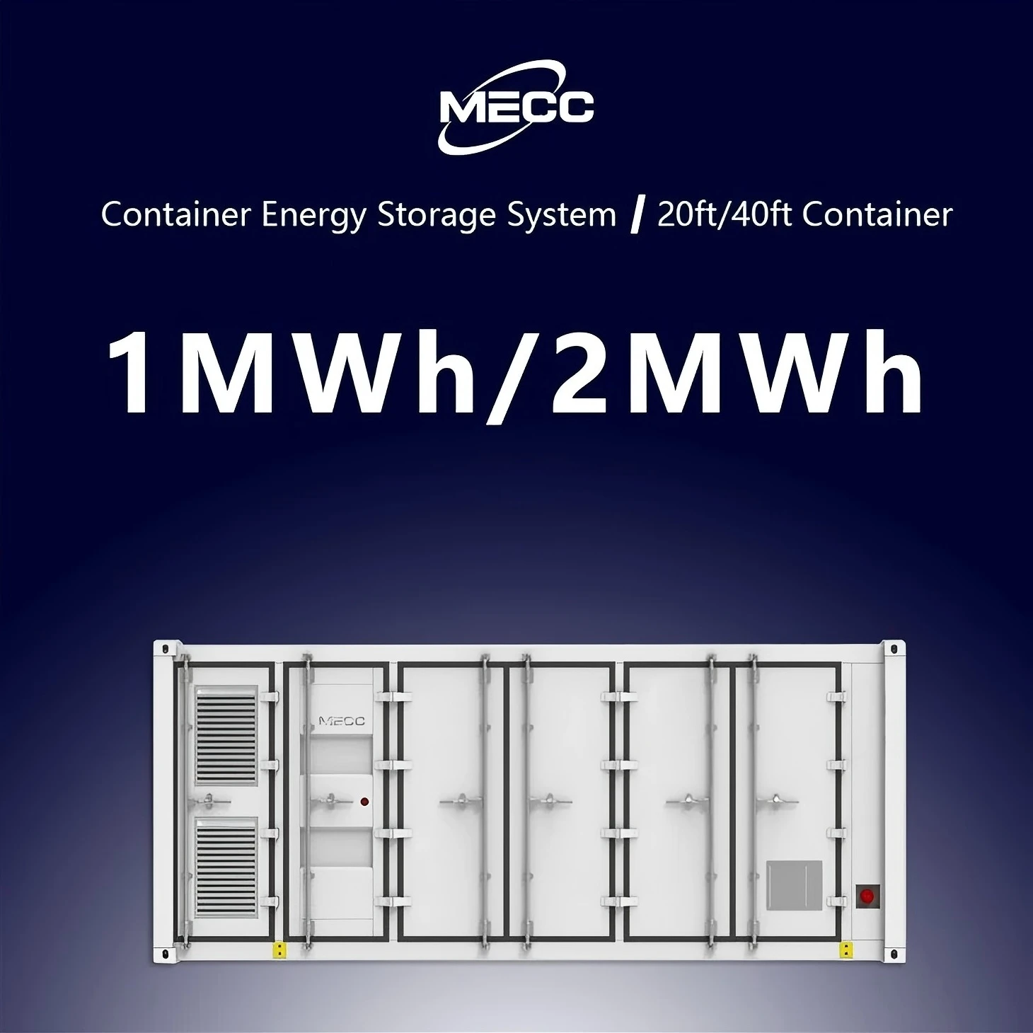
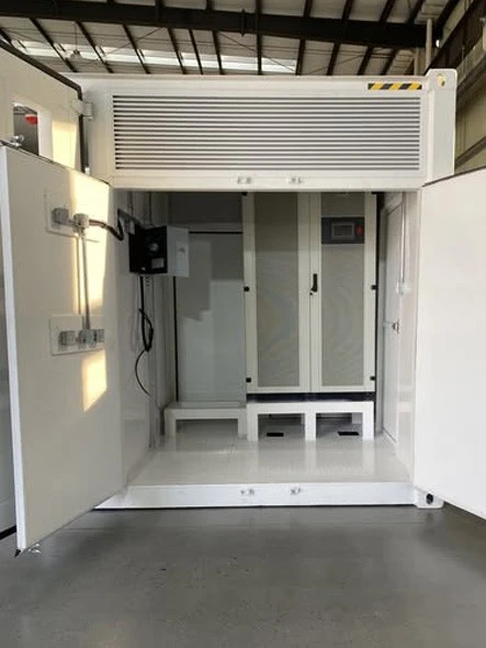
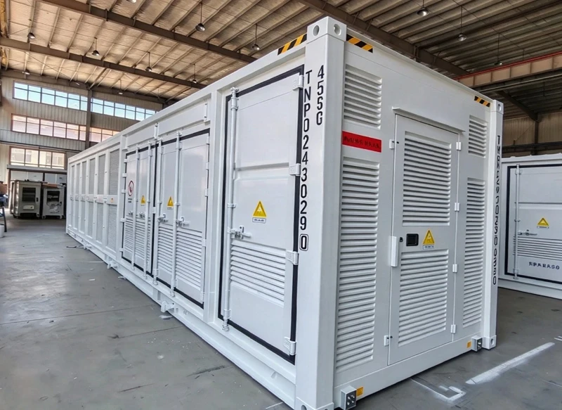
500KW/1MW 1MWh/2MWh Battery Energy Storage System Container
The 500kW/1MW 1MWh/2MWh Battery Energy Storage System Container is a turn‑key utility‑grade energy storage solution housed in standard 20ft or 40ft shipping containers, integrating bidirectional PCS, A‑grade LiFePO4 battery clusters, master BMS, liquid‑cooled thermal management, gas fire suppression, high‑voltage distribution and EMS energy management system with full factory pre‑assembly and pre‑commissioning. Requiring only foundation construction and high‑voltage cable connection for on‑site commissioning, it supports flexible power‑capacity configuration and multi‑container parallel expansion, delivering core capabilities of peak‑shaving and load shifting, renewable energy smoothing, frequency‑voltage grid support, islanded micro‑grid operation and large‑scale emergency backup. Featuring IP54 enclosure protection and comprehensive multi‑layer safety mechanisms, it adapts to diverse harsh outdoor environments, and is widely deployed for ground‑mounted PV power stations, industrial parks, mining operations, island microgrids and grid‑side auxiliary service projects to stabilize grid fluctuations, boost renewable energy utilization and reduce comprehensive energy costs.