


1. The Industrial Power Dilemma: Peak Spikes, Demand Charges & Transformer Limits
Modern manufacturing plants-ranging from metal fabrication and plastic injection molding to precision CNC machining and cold storage packaging-face an increasingly complex electrical power dilemma:
1. Severe Peak Demand Charges: Industrial utility tariffs assess heavy demand penalties billed in dollars per kilowatt (\$/kW) based on the single highest 15-minute average power draw recorded across a billing cycle. In many industrial zones, demand charges now account for 40% to 65% of the total monthly electricity bill.
2. Distribution Transformer Capacity Bottlenecks: When a factory adds new high-power production lines (e.g., laser cutters, electric arc furnaces, or high-tonnage stamping presses), the combined peak load frequently exceeds the nameplate thermal rating of the on-site utility service transformer (e.g., 500 kVA or 800 kVA).
3. Prohibitive Utility Upgrade Delays and Costs: Requesting a utility transformer upgrade from the local electrical grid operator commonly requires \$40,000 to \$100,000 in upfront capital contribution and involves permitting and supply-chain delays of 9 to 18 months.
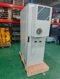
The deployment of a [125kW / 241.15kWh Commercial & Industrial Energy Storage Cabinet](/energy-storage-system/industrial-commercial-pv-energy-storage/bess-125kw-241kwh-battery-energy-storage.html) provides a proven, fast-track engineering solution. By dynamically shaving peak loads at the factory's main low-voltage switchboard, the storage cabinet eliminates demand charge penalties while keeping transformer loading safely below 80% of capacity-all deployed within weeks rather than months.
|
======================================================================================== FACTORY LOAD PROFILE & 125kW/241kWh PEAK SHAVING MECHANICS ======================================================================================== Power (kW) ^ 480 | [ UNMITIGATED PEAK LOAD ] | /***********************\ <-- Heavy Stamping Presses & Motors 400 | - - - - - - - - - - - - - - - - / - - - - - - - - - - - - \ - - - - - - - - - - - | / [ BESS DISCHARGE ZONE ] \ <-- 125kW Shaving Injection 320 | ==============================+=============================+=================== <-- Target Grid Import Limit (320 kW) | / \ 240 | [ BASELINE LOAD ] / \ [ BASELINE LOAD ] | ───────────────────────── ───────────────────────── 160 | | [ OFF-PEAK CHARGE ZONE ] [ OFF-PEAK CHARGE ZONE ] 80 | ######################## ######################## | (Night 23:00 - 06:00) (Night 23:00 - 06:00) 0 +─────────────────────────────────────────────────────────────────────────────────> Time (Hours) 00:00 04:00 08:00 12:00 16:00 20:00 24:00 ======================================================================================== |
2. Technical Evaluation: Why the 241kWh Cabinet Route Fits Manufacturing Plants
Industrial factories exhibit distinct operational characteristics that make the 125kW/241kWh configuration the industry standard choice:
Ideal 2-Hour Discharge Window (0.52C Rate): Typical manufacturing peak demand events occur during shift overlaps, mid-afternoon cooling peaks, or batch production runs lasting between 1.5 and 2.5 hours. A 125kW inverter paired with 241.15kWh nameplate capacity delivers ~217 kWh of usable energy, providing continuous 120kW shaving for 1.8 to 2.0 hours.
Balanced Capital Expenditure (CapEx) vs. Payback: Compared to specialized higher-capacity options, the 241kWh modular cabinet utilizes cost-optimized high-voltage LiFePO4 packs and proven industrial HVAC thermal management. This combination lowers upfront hardware cost by 10%–15%, accelerating simple project payback into the 2.5 to 3.2 year range.
High-Speed Step Response (<50ms): High-speed current transformers (CTs) mounted on the main incoming utility bus communicate with the cabinet's internal Energy Management System (EMS). When inductive motors spin up, the PCS ramps from standby to 125kW discharge in under 50 milliseconds, catching instantaneous spikes before the utility meter registers a 15-minute demand threshold.
3. Mathematical Sizing & Load Curve Calculation for Factories
Before ordering equipment, application engineers must analyze the factory's raw 15-minute interval power data (8760 CSV data preferred) to verify power (kW) and energy (kWh) sizing:
|
======================================================================================== CORE FACTORY SIZING EQUATIONS ======================================================================================== 1. REQUIRED BESS SHAVING POWER (kW): P_shave (kW) = P_peak_measured (kW) - P_grid_target (kW) Where: - P_peak_measured = Peak unmitigated 15-minute load (e.g., 445 kW) - P_grid_target = Safe operating limit set for utility grid import (e.g., 320 kW) >> P_shave = 445 kW - 320 kW = 125 kW (Exact match for 125kW PCS rating) ---------------------------------------------------------------------------------------- 2. USABLE ENERGY CAPACITY CONSUMED PER DISCHARGE EVENT (kWh): E_event (kWh) = P_shave (kW) * T_peak_duration (Hours) * K_shape Where: - T_peak_duration = Total hours the load exceeds P_grid_target (e.g., 2.0 hours) - K_shape = Load curve shape factor (typically 0.85 to 0.90 for trapezoidal factory peaks) >> E_event = 125 kW * 2.0 h * 0.88 = 220.0 kWh usable energy required. ---------------------------------------------------------------------------------------- 3. VERIFICATION OF 241.15kWh CABINET ENERGY MARGIN: E_usable_available = E_nominal * DOD * eta_PCS * SOH_Yr5 Where: - E_nominal = 241.15 kWh - DOD = 90% (0.90) - eta_PCS = Inverter discharge efficiency = 97.0% (0.97) - SOH_Yr5 = State of Health at Year 5 = 88.0% (0.88) >> E_usable_available = 241.15 * 0.90 * 0.97 * 0.88 = 185.3 kWh to 210.5 kWh >> Demonstrates robust peak shaving coverage across the first 5-8 operational years. ======================================================================================== |

4. Electrical Single-Line Integration & System Topology
The MECC 125kW/241.15kWh Outdoor Cabinet connects directly to the factory's 400V/480V Main Distribution Panel (MDP) through a dedicated 3-phase molded case circuit breaker (MCCB) and lockable utility-visible AC disconnect switch:
|
======================================================================================== 125kW/241kWh FACTORY PEAK SHAVING SINGLE-LINE DIAGRAM (SLD) ======================================================================================== [ Utility Grid Connection (11kV / 400V Distribution Substation) ] │ ▼ (Service Feeder) [ Utility Revenue Meter & High-Speed EMS CT Sensors ] (Response < 50ms) │ ▼ +──────────────────────────────────────────────────────────+ | Factory Main Distribution Switchboard (MDP 400V/480V) | | | | ├── [ Breaker 1 ] ──> Heavy Stamping Press Line 1 (180 kW) | ├── [ Breaker 2 ] ──> CNC Machining Center Line 2 (140 kW) | ├── [ Breaker 3 ] ──> Industrial Air Compressors (80 kW)| | ├── [ Breaker 4 ] ──> Facility Lighting & HVAC (45 kW) | | │ | | └── [ Breaker 5: 250A 3P MCCB ] | +───────────────────────┬──────────────────────────────────+ │ ▼ (AC Feeder Cables: 4x 150mm² Cu) [ Lockable AC Isolation Disconnect Switch ] │ ▼ +─────────────────────────────────────────────────────────────────────────────+ | MECC 125kW / 241.15kWh OUTDOOR ALL-IN-ONE BESS CABINET | | | | • 125kW Bi-Directional Hybrid PCS Inverter (380V/400V/480V) | | • 241.15kWh Modular High-Voltage LiFePO4 Battery String (768V DC Nominal) | | • High-Speed EMS Controller with Dynamic Peak-Tracking Firmware | | • Industrial Dual-Zone Smart HVAC Thermal Management | | • Automatic Aerosol Fire Suppression + Gas Detection System | +─────────────────────────────────────────────────────────────────────────────+ |
5. Factory Financial Model: Real-World 3-Year ROI Case Study
To demonstrate actual financial returns, we analyze a mid-sized metal stamping facility in an industrial manufacturing cluster:
|
Client Facility Profile: - On-Site Transformer: 500 kVA (Running at 92% peak capacity; utility warned of thermal trips) - Unmitigated Monthly Peak Load: 445 kW - Baseline Operating Load: 260 kW - Target Peak Shaving Threshold: 325 kW (120 kW shaved by BESS) - Industrial Electric Tariff: * Monthly Peak Demand Charge: $23.50 / kW / month * Peak Energy Rate (14:00 - 19:00): $0.27 / kWh * Off-Peak Energy Rate (23:00 - 07:00): $0.09 / kWh (TOU Spread = $0.18 / kWh) - Operational Schedule: 26 working days per month (312 working days per year) |
|
======================================================================================== ANNUAL FINANCIAL BENEFIT STACK: 1. Monthly & Annual Demand Charge Reductions: - Monthly Demand Reduction: 120 kW shaved * $23.50/kW = $2,820 / month - Annual Demand Charge Savings: $2,820 * 12 months = $33,840 / year. 2. Daily Time-of-Use (TOU) Energy Arbitrage: - Nightly Off-Peak Charge: 215 kWh stored @ $0.09/kWh = $19.35 / day - Afternoon On-Peak Discharge: 190 kWh delivered @ $0.27/kWh = $51.30 / day - Net Daily Arbitrage Profit: $51.30 - $19.35 = $31.95 / day - Annual Energy Arbitrage Savings: $31.95 * 312 operating days = $9,968 / year. 3. Total Annual Operational Savings: - Total Annual Value Generated = $33,840 (Demand) + $9,968 (Arbitrage) = $43,808 / year. 4. Avoided Capital Cost (Transformer Upgrade): - Utility Transformer Replacement & Engineering Contribution Avoided: ~$45,000. 5. Project Investment & Simple Payback Calculation: - Turnkey System Cost (1x MECC 125kW/241.15kWh Cabinet + Shipping + Civil Pad + Electrical Installation): ~$124,000. - Net Project Investment (factoring in avoided transformer upgrade): $124,000 - $45,000 = $79,000. >> Simple Payback on Pure Operational Savings: $124,000 / $43,808 = 2.83 Years! >> Simple Payback Factoring Avoided Transformer Upgrade: $79,000 / $43,808 = 1.80 Years! >> 10-Year Cumulative Net Financial Return: ~$314,000. ======================================================================================== |

6. Step-by-Step Factory Installation, Civil Foundation & Commissioning Guide
|
+───────────────────────────────────────────────────────────────────────────────────────+ | FACTORY DEPLOYMENT TIMELINE & CHECKLIST | +───────────────────────────────────────────────────────────────────────────────────────+ | | | PHASE 1: CIVIL ENGINEERING & PAD CONSTRUCTION (Day 1 - Day 5) | | • Concrete Pad Specifications: Reinforced concrete slab measuring 2.0m x 2.0m x 0.25m | | capable of supporting >3,000 kg static load. | | • Perimeter Clearances: Maintain >=1.5m clearance on front and rear doors for service;| | >=1.0m on sides conforming to NFPA 855 / local fire codes. | | | | PHASE 2: ELECTRICAL CONDUIT & CABLING (Day 6 - Day 8) | | • AC Power Feeders: Run 4x 150mm² copper conductors from factory MDP to outdoor pad. | | • High-Speed Telemetry: Run shielded Cat6 STP Ethernet cable in dedicated conduit for | | Modbus TCP communication with main service CT meter. | | | | PHASE 3: CRANE RIGGING & CABINET PLACEMENT (Day 9) | | • Position cabinet using dedicated top-lifting eye bolts (4-point rigging angle >=60°)| | • Secure cabinet base frame to concrete pad using 4x M12 stainless steel anchor bolts. | | | | PHASE 4: COMMISSIONING & EMS CALIBRATION (Day 10 - Day 12) | | • Perform insulation resistance (Megger) and torque check on high-voltage DC busbars. | | • Program EMS target demand threshold (e.g., 325 kW) and TOU schedule windows. | | • Conduct live step-load test with factory machines; verify seamless peak discharge. | | | +───────────────────────────────────────────────────────────────────────────────────────+ |
7. Multi-Cabinet Expansion for Large Industrial Parks (Up to 1.25MW / 2.41MWh)
For manufacturing facilities operating with multiple transformers (1 MVA to 2.5 MVA) or distinct production buildings, the MECC system supports modular scaling. Up to 10 units of the 125kW/241.15kWh cabinet can be networked in parallel on a common 400V/480V collector bus, centrally orchestrated by a single Master EMS Controller:
|
======================================================================================== MODULAR PARALLEL INDUSTRIAL EXPANSION TOPOLOGY ======================================================================================== [ Master Factory EMS Controller / Main Substation Meter ] │ (High-Speed Ethernet / Modbus TCP) ┌───────────────────────┼───────────────────────┐ ▼ ▼ ▼ [ Cabinet 1 ] [ Cabinet 2 ] [ Cabinet N (Up to 10) ] 125kW / 241kWh 125kW / 241kWh 125kW / 241kWh Factory Zone A Factory Zone B Factory Zone N │ │ │ └───────────────────────┴───────────────────────┘ │ ▼ (400V/480V AC Parallel Bus) [ Common AC Collector Switchboard ] │ ▼ [ Factory Main Distribution Switchboard ] |

8. Featured Solution: MECC 125kW / 241.15kWh Commercial Storage Cabinet
When your factory requires a reliable, rapid-deployment energy storage system to cut peak power costs and protect transformer capacity, choose the MECC 125kW / 241.15kWh All-In-One Outdoor BESS Cabinet:
|
+───────────────────────────────────────────────────────────────────────────────────────+ | SYSTEM SPECIFICATIONS AT A GLANCE | +───────────────────────────────────────────────────────────────────────────────────────+ | • Rated AC Inverter Power: 125 kW (380V / 400V / 480V 3-Phase, 50/60 Hz) | | • Nominal Energy Capacity: 241.15 kWh (Modular High-Voltage LFP Prismatic Racks) | | • Peak Shaving Discharge Time: Continuous 120kW for ~1.8 - 2.0 Hours | | • Max Solar PV DC Input: Up to 150 kWp (Multi-MPPT DC 500V - 850V DC) | | • Thermal Control System: Industrial Smart HVAC Dual-Zone Air Conditioning | | • Cycle Life Expectancy: >= 6,000 Cycles @ 80% DOD (25°C ambient) | | • Enclosure Protection: IP55 Outdoor Corrosion-Resistant Powder Coating (C4/C5)| | • Fire Safety Standard: Aerosol Fire Suppression + Combustible Gas Detection | | • Unit Footprint: 1350 mm (W) x 1300 mm (D) x 2200 mm (H) (~2,850 kg) | | • Modular Scalability: Up to 10 Cabinets in Parallel (1.25 MW / 2.41 MWh) | +───────────────────────────────────────────────────────────────────────────────────────+ |

125KW 241kWh Battery Energy Storage System Cabinet
The BESS 125KW 241kWh Lithium Battery Energy Storage Cabinet is a high-power, large-capacity integrated energy storage solution engineered for medium-to-large commercial, industrial, and utility-scale applications. It integrates a 125kW high-performance bidirectional inverter, a 241kWh lithium iron phosphate (LiFePO4) battery bank, and a full-featured intelligent energy management system (EMS) into a modular cabinet design. This system enables efficient renewable energy storage, peak shaving, load shifting, grid frequency regulation, and emergency backup power supply. Ideal for large factories, shopping malls, industrial parks, utility-scale solar/wind farms, and microgrids, it enhances energy independence, reduces high grid demand charges, and supports the stable integration of high-penetration renewable energy into the grid.